Configuration of ieee 488 interfaces – Measurement Computing Personal488 rev.3.0 For DOS & Windows 3.Xi User Manual
Page 212
II. SOFTWARE GUIDES - 10. Driver488/W31
10B. Installation & Configuration
Personal488 User’s Manual, Rev. 3.0
II-197
Configuration of IEEE 488 Interfaces
Note:
The Driver488/W31
supports only the
IEEE interface.
The following
Driver488/W31 figure
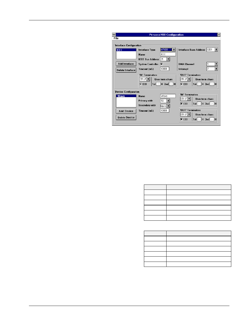
displays the configuration of:
An MP488 IEEE 488.2
interface in the upper screen
section, and a
WAVE
external
device in the lower screen
section.
For additional information on
using more than one
interface, refer to the final
topic “Multiple Interface
Management” in the Sub-
Chapter “Installation &
Configuration” of Chapter 8.
Once an interface is selected,
the fields and default entries
which display in the
configuration window depend on the device type specified. The configuration parameters of the IEEE
interface, shown in the figure, are as follows:
Configuration Parameters
•
Name: This field is a descriptive instrument name which is manually assigned by the user. This
must be a unique name. Typically, IEEE is used.
•
IEEE Bus Address: This is the setting for the IEEE bus address of the board. It will be checked
against all the instruments on the bus for conflicts. It must be a valid address from
0
to
30
.
•
DMA: A direct memory access (DMA)
channel can be specified for use by the I/O
interface card. If DMA is to be used, select
a channel as per the hardware setting. If no
DMA is to be used, select NONE. The
NB488 does not support DMA, therefore the
DMA field will not display if this device
type is used. Valid settings are displayed in
the table.
•
Interrupt: A hardware interrupt level
(IRQ) can be specified to improve the
efficiency of the I/O adapter control and
communication using Driver488/W31. For
DMA operation or any use of
OnEvent
and
Arm
functions, an interrupt level must be
selected. Boards may share the same
interrupt level. If no interrupt level is to be
used, select NONE. Valid interrupt levels
depend on the type of interface. Possible settings are shown in the table.
•
SysController: This field determines whether or not the IEEE 488 interface card is to be the
System Controller. The System Controller has ultimate control of the IEEE 488 bus, and the
ability of asserting the Interface Clear (
IFC
) and Remote Enable (
REN
) signals. Each IEEE 488
bus can have only one System Controller. If the board is a Peripheral, it may still take control of
Configuration Utility Screen with MP488 Board
I/O Board
Specified DMA Channel
GP488B
1, 2, 3 or none
AT488
1, 2, 3, 5, 6, 7 or none
MP488
1, 2, 3, 5, 6, 7 or none
MP488CT
1, 2, 3, 5, 6, 7 or none
NB488
Not applicable
CARD488
Not applicable
I/O Board
Specified Interrupt Level
GP488B
levels 2-7 or none
AT488
levels 3-7, 9-12, 14-15 or none
MP488
levels 3-7, 9-12, 14-15 or none
MP488CT
levels 3-7, 9-12, 14-15 or none
NB488
level 7 for LPT1, level 5 for LPT2
CARD488
levels 3-7, 9-12, 14-15 or none