Measurement Computing Personal488 rev.3.0 For DOS & Windows 3.Xi User Manual
Page 56
II. SOFTWARE GUIDES - 8. Driver488/DRV
8B. Installation & Configuration
Personal488 User’s Manual, Rev. 3.0
II-41
bus and, when it is done, pass control back to the System Controller or another computer, which
then becomes the active controller. If the board will be operating in Peripheral mode (not System
Controller), select NO in this field.
•
LightPen: This field determines whether the
LIGHT PEN
command is to be used. If selected, it
will disable the detection of interrupts via setting the light pen status. The default is light pen
interrupt enabled.
•
Timeout (ms): The time out period is the amount of time that data transfers wait before assuming
that the device does not transfer data. If the time out period elapses while waiting to transfer data,
an error signal occurs. This field is the default timeout for any bus request or action, measured in
milliseconds. If no timeout is desired, the value may be set to zero.
•
Device Type: This field specifies the type of board or module (such as GP488, MP488CT or
NB488) represented by the IEEE device name selected.
I/O Address
•
IEEE 488: This field is the I/O base address which sets the addresses used by the computer to
communicate with the IEEE interface hardware on the board. The address is specified in
hexadecimal and can be
02E1
,
22E1
,
42E1
or
62E1
.
Note: This field does not apply to the NB488. Instead, the NB488 uses the I/O address of the data
register (the first register) of the LPT port interface, typically
0x0378
.
•
Digital I/O: This field is the base address of the Digital I/O registers. It is only applicable for
MP488 and MP488CT boards. Note that the Digital I/O SCPI communication parameters are
configured as an external device. Refer to the “Section I: Hardware Guides” for more information.
•
Counter/Timer: This field is the base address of the Counter/Timer registers. It is only
applicable for MP488CT boards. Note the Counter/Timer SCPI communication parameters are
configured as an external device. Refer to the “Section I: Hardware Guides” for more information.
•
Bus Terminators: The IEEE 488 bus terminators specify the characters and/or end-or-identify
(
EOI
) signal that is to be appended to data that is sent to the external device, or mark the end of
data that is received from the external device.
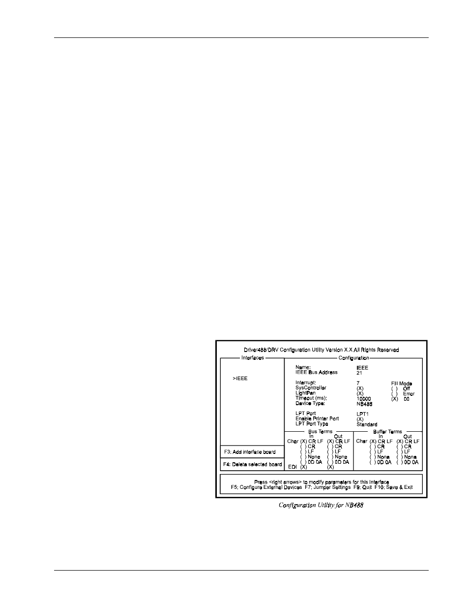
This second Driver488/DRV
configuration example displays
an IEEE interface with the
NB488 interface module
specified. This screen
resembles the previous IEEE
interface example with the
exception of 3 different
configuration parameters which
are described below.
Configuration Parameters
•
LPT Port: The LPT port
is the external parallel port
to be connected to the
NB488. Valid selections
are:
LPT1
,
LPT2
or
LPT3
.
This field takes the place
of the I/O Address field.
•
Enable Printer Port:
Because most laptop and notebook PCs provide only one LPT port, the NB488 offers LPT pass-
through for simultaneous IEEE 488 instrument control and printer operation. If this option is
selected, a printer connected to the NB488 will operate as if it were connected directly to the LPT
port. If not enabled, then the printer will not operate when the NB488 is active. The disadvantage