Configuration of ieee 488 external devices – Measurement Computing Personal488 rev.3.0 For DOS & Windows 3.Xi User Manual
Page 156
II. SOFTWARE GUIDES - 9. Driver488/SUB
9B. Installation & Configuration
Personal488 User’s Manual, Rev. 3.0
II-141
•
DCD Timeout: The driver supports 3 hardware handshake lines: Data Carrier Detect (
DCD
), Data
Set Ready (
DSR
), and Clear To Send (
CTS
). Each line can be individually designated to be
ignored, used with no specified timeout, or used with a selected timeout. The timeout is selected
by specifying the number of milliseconds to wait for the indicated condition to become satisfied.
•
Timeout (ms): The time out period is the amount of time that data transfers wait before assuming
that the device does not transfer data. If the time out period elapses while waiting to transfer data,
an error signal occurs. This field is the default timeout for any bus request or action, measured in
milliseconds. If no timeout is desired, the value may be set to zero.
•
Device Type: This field specifies the type of device represented by the serial external device
name selected.
•
I/O Address: The I/O Address is the
computer bus address for the board. It is set to
default values during the initial installation.
These values, as listed in the table, can be
changed. However, using the pre-selected
values is recommended. Any conflict will be
noted by a pop-up help screen.
•
Bus Terminators: The bus terminators specify the characters to be appended to data that is sent
to the external device, or mark the end of data that is received from the external device.
Configuration of IEEE 488 External Devices
Configuration of IEEE 488 external devices under Driver488/SUB is done by editing an initialization
file that stores the specific configuration information about all of the configured external devices. The
configuration for each device is set when the Driver488/SUB loads itself into memory and is present at
the start of the application program.
Each external device requires a handle to communicate with Driver488/SUB. An external device
handle is a means of maintaining a record about 3 configurable items: its IEEE 488 bus address, its
IEEE 488 bus terminators, and its time out period. Any communication with the external device uses
these three items. The different configurable items are listed in the following figure. These items
define the external device. All external devices have either a default value or a user supplied value for
the different fields. All fields can be changed by Driver488/SUB commands during program
execution.
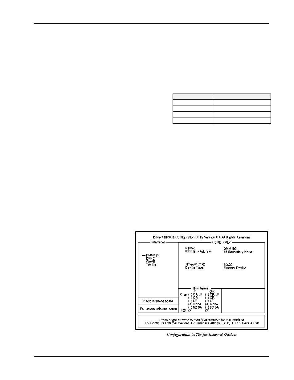
The following figure displays
the configuration screen of an
external device named
DMM195
.
When configuring an IEEE
interface, this screen can be
accessed by selecting
Configure External
Devices
.
To add additional devices, use
. Note this external
device screen is also used to
configure MP488CT Digital
I/O (
DIGIO
) and
Counter/Timers (
TIMER
).
The following parameters are
available for modification:
Configuration Parameters
•
Name: External device
names are user defined names which are used to convey the configuration information about each
I/O Comm.
Default Address Values
COM1
typically address 3F8
COM2
typically address 2F8
COM3
typically address 3E8
COM4
typically address 2E8