Measurement Computing Personal488 rev.3.0 For DOS & Windows 3.Xi User Manual
Page 27
I. HARDWARE GUIDES
2. Personal488 (with GP488B)
Personal488 User’s Manual, Rev. 3.0
I-11
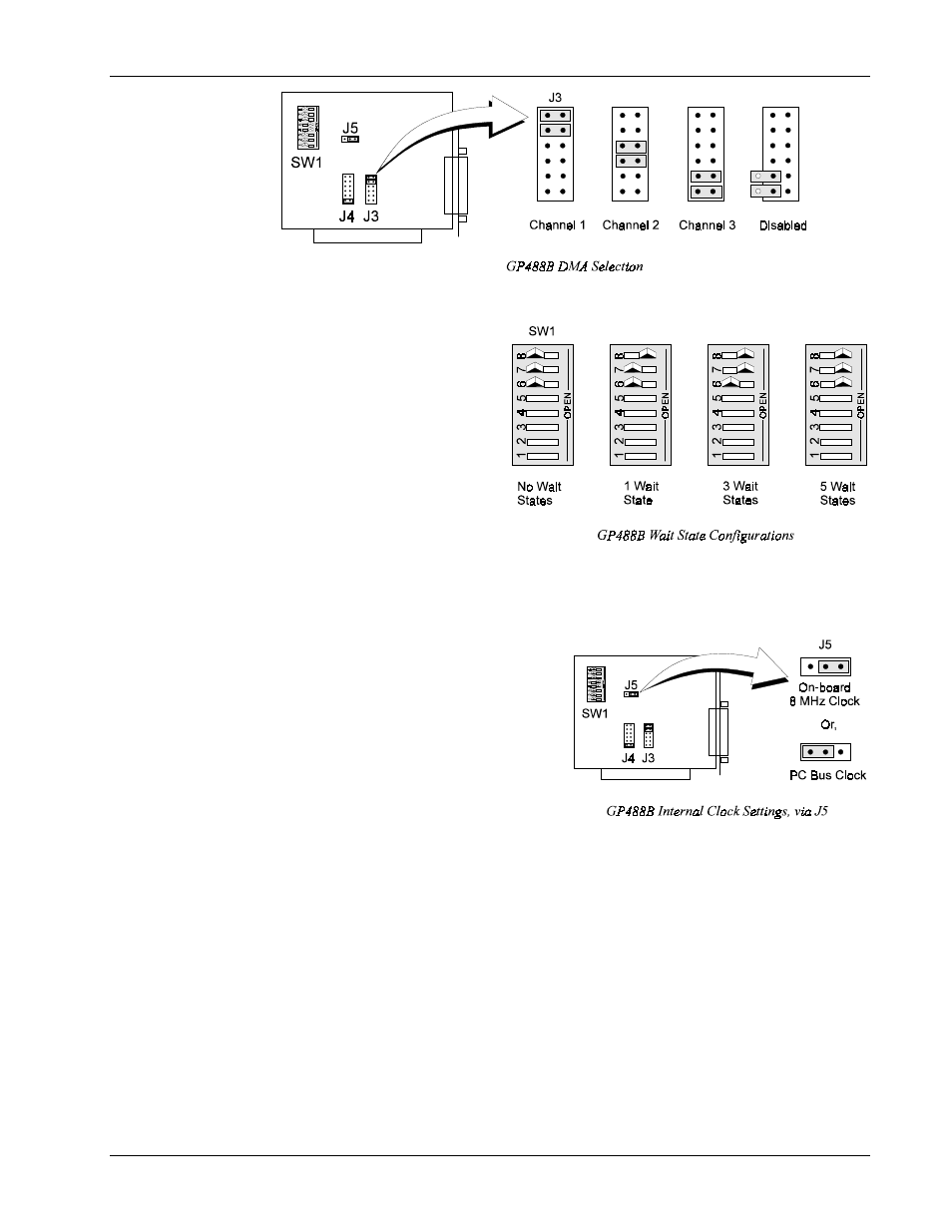
Wait State Configuration
The GP488B is fast enough to be
compatible with virtually every
PC/XT/AT-compatible computer on the
market. Even if the computer is very fast,
the processor is normally slowed to 8MHz
or below when accessing the I/O channel.
If the I/O channel runs faster than 8 MHz,
it may be faster than the GP488B card. If
you suspect this is a problem, the computer
can be made to wait for the GP488B by
enabling wait states. Increasing the number
of wait states slows down access to the
GP488B card, but the overall performance
degradation is usually only a few percent.
Internal Clock Selection
The IEEE 488 bus interface circuitry requires a
master clock. This clock is normally connected to an
on-board 8 MHz clock oscillator. However, some
compatible IEEE 488 interface boards connect this
clock to the PC’s own clock signal. Using the PC
clock to drive the IEEE 488 bus clock is not
recommended because the PC clock frequency
depends on the model of computer. A standard PC
has a 4.77 MHz clock, while an AT might have a 6
MHz or 8 MHz clock. Other manufacturers’
computers may have almost any frequency clock. If
you are using a software package designed for an interface board (that derived its clock from the PC
clock) and you need to do the same to use GP488B with that particular software, the clock source can
be changed. However, the clock frequency must never be greater than 8 MHz, and clock frequency
must be correctly entered in the Driver488 software.
Board Installation
The IEEE 488 interface board(s) are installed into expansion slots inside the PC’s system unit. PC/AT-
compatible computers have two types of expansion slots: 8-bit (with one card-edge receptacle), and 16-
bit (with two card-edge receptacles). Eight-bit boards, such as the IEEE 488 interface boards, may be
used in either type of slot, 8- or 16-bit. Some machines may have special 32-bit memory expansion
slots which should not be used for IEEE 488 interface boards.
Install each IEEE 488 interface board into the expansion slots as follows: Ensure the PC is turned off
and unplug the power cord. Remove the cover mounting screws from the rear of the PC system unit.
Remove the system unit cover by sliding it forward and tilting it upward.