Measurement Computing Personal488 rev.3.0 For DOS & Windows 3.Xi User Manual
Page 31
I. HARDWARE GUIDES
3. Personal488/AT
Personal488 User’s Manual, Rev. 3.0
I-15
Interrupts 10 through 15 are only available in a 16-bit slot on an AT-class machine. Interrupt 9
becomes synonymous with interrupt 2 when used in a PC/XT bus. The selected interrupt may be
shared among several AT488s in the same PC/AT chassis. The AT488 adheres to the “AT-style”
interrupt sharing conventions. When the AT488 requires service, the IRQ jumper determines which PC
interrupt level is triggered. When an interrupt occurs, the interrupting device must be reset by writing
to an I/O address which is different for each interrupt level. The switch settings determine the I/O
address to which the board’s interrupt rearm circuitry responds. The IRQ jumper and switch settings
must both indicate the same interrupt level for correct operation with interrupts. The previous figure
shows the settings for selected interrupts.
DMA Channel Selection
Direct Memory Access (DMA) is a high-speed method of transferring data from or to a peripheral, such
as a digitizing oscilloscope, to or from the PC’s memory. The AT class machine has seven DMA
channels. Channels 0-3 (8-bit), 5, 6, and 7 (16-bit) are available only in a 16-bit slot on a PC/AT-class
machine. Channel 2 is usually used by the floppy disk controller, and is unavailable. Channel 3 is
often used by the hard disk controller in PCs, XTs, and the PS/2 with the ISA bus, but is usually not
used in ATs. Channels 5 through 7 are 16-bit DMA channels. They offer the highest throughput (up to
1 Megabyte per second). Channels 0 through 3 are 8-bit DMA channels. Although slower, they offer
compatibility with existing GP488B applications that only made use of 8-bit DMA channels. Under
some rare conditions, it is possible for high-speed transfers on DMA channel 1 to demand so much of
the available bus bandwidth that simultaneous access of a floppy controller will be starved for data due
to the relative priorities of the two channels. Both the DRQ and DACK jumpers must be set to the
desired DMA channel for proper operation. Configure the board according to which DMA channel is
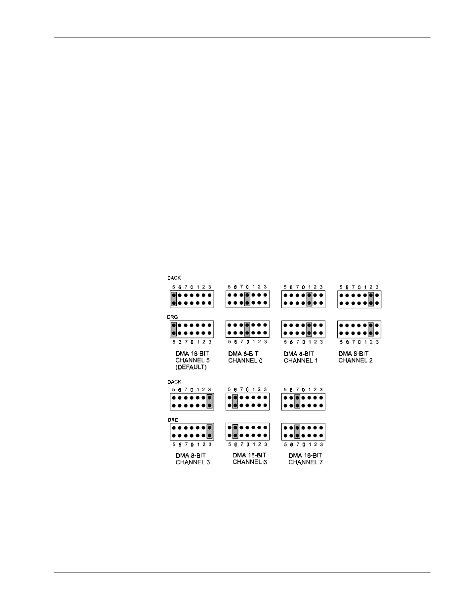
available. The following figure shows settings for selecting the DMA channels.
Personal488/AT DMA Selection
Board Installation
The IEEE 488 interface board(s) are installed into expansion slots inside the PC’s system unit. PC/AT-
compatible computers have two types of expansion slots: 8-bit (with one card-edge receptacle), and 16-
bit (with two card-edge receptacles). Eight-bit boards, such as the IEEE 488 interface boards, may be
used in either type of slot, 8- or 16-bit. Some machines may have special 32-bit memory expansion
slots which should not be used for IEEE 488 interface boards.