Configuration of serial interfaces – Measurement Computing Personal488 rev.3.0 For DOS & Windows 3.Xi User Manual
Page 155
9B. Installation & Configuration
II. SOFTWARE GUIDES - 9. Driver488/SUB
II-140
Personal488 User’s Manual, Rev. 3.0
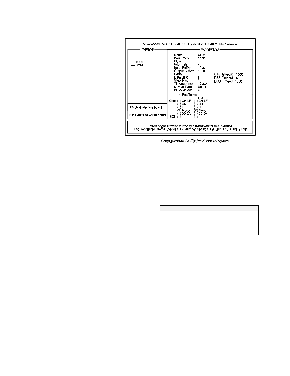
Configuration of Serial Interfaces
The following Driver488/SUB
screen displays the
configuration of a serial (COM)
interface.
To add another serial interface,
select
.
The following serial interface
parameters are available for
modification.
Configuration Parameters
•
Name: This field is a
descriptive instrument
name which is manually
assigned. This must be a
unique name.
•
Baud Rate: The
allowable Data Rates range
from 75 to 115.2K and all
standard rates therein. This includes: 75, 110, 150, 300, 600, 1200, 1800, 2400, 4800, 9600,
19.2K, 38.4K, 57.6K, and 115.2K. Slower processors may have difficulty at the higher data rates
because of the amount of processing required for terminator, end of buffer, and fill processing.
•
Flow:
X-ON/X-OFF
is supported. With this configured, Driver488/SUB scans incoming
characters for an
X-OFF
character. Once it is received, no more characters are transmitted until an
X-ON
character is received. The driver also issues an
X-OFF
to ask the attached device to stop
sending when its internal buffer becomes three-quarters full and issues an
X-ON
when its buffer has
emptied to one-quarter full.
•
Interrupt: A hardware interrupt level can be
specified to improve the efficiency of the I/O
adapter control and communication using
Driver488/SUB. For any use of
OnEvent
and
Arm
functions, an interrupt level must be
selected. If no interrupt level is to be used,
select NONE. Valid interrupt levels depend
on the device type:
•
Input Buffer: This field is used to enter the buffer sizes for I/O.
•
Output Buffer: This field is used to enter the buffer sizes for I/O.
•
Parity: Parity can be EVEN, ODD, NONE, MARK, or SPACE.
•
CTS Timeout: The driver supports 3 hardware handshake lines: Data Carrier Detect (
DCD
), Data
Set Ready (
DSR
), and Clear To Send (
CTS
). Each line can be individually designated to be
ignored, used with no specified timeout, or used with a selected timeout. The timeout is selected
by specifying the number of milliseconds to wait for the indicated condition to become satisfied.
•
Data Bits: Data formats from 5 though 8 Data Bits are supported.
•
DSR Timeout: The driver supports 3 hardware handshake lines: Data Carrier Detect (
DCD
), Data
Set Ready (
DSR
), and Clear To Send (
CTS
). Each line can be individually designated to be
ignored, used with no specified timeout, or used with a selected timeout. The timeout is selected
by specifying the number of milliseconds to wait for the indicated condition to become satisfied.
•
Stop Bits: With 6, 7, or 8 Data Bits specified, either 1 or 2 Stop Bits are allowed. With 5 Data
Bits specified, 1 or 1.5 Stop Bits may be selected.
I/O Comm.
Typical Interrupt Level
COM1
typically level 4
COM2
typically level 3
COM3
typically level 4 or 5
COM4
typically level 2 or 3