Measurement Computing DASYLab User Manual
Page 70
B-16 Configuring DASYLab for Daq Devices
989593
DASYLab – Standard Driver
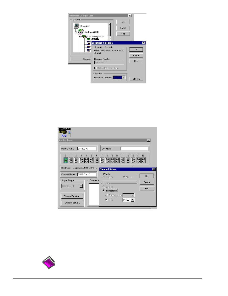
When using a DBK9, an 8-channel card, you must select 2 as the number of devices.
After adding all of your DBK cards to your hardware setup, add your analog input modules to your
worksheet as follows:
1. On your DASYLab Worksheet, go to Modules, then Analog Input. A selection menu that lists all
hardware devices will appear.
2. After a module is added to the worksheet, double-click on it. In this example we have double-clicked
on the “DBK9:0 AI” module icon. The following screen image resulted.
Setting Channel at Connector 0 as an RTD
3.
Activate desired channels by left-button clicking them. Note that a single right-click deactivates the
channel.
4. Click the Channel Setup button (see previous figure) to make channel setup selections.
Note that conversion of voltage units to engineering units can be made using the channel scaling
within the analog input module or the scaling module outside the analog input module. After
completing your hardware setup, you are ready to add icons to your worksheet.
Reference Note:
DBK19 and DBK52 users need to refer to Appendix C.