Supplemental information …… b-15, Supplemental information – Measurement Computing DASYLab User Manual
Page 69
DASYLab – Standard Driver
989593
Configuring
DASYLab for Daq Devices B-15
Supplemental Information
Some of the material presented in this section is redundant. The material is included to provide a better
understanding of hardware setup through use of screen images.
Using P1 Analog Inputs and DBK Signal Conditioning
An example using a DaqBoard/2000 and a DBK9
1. Select Experiment
⇒
Hardware setup. This displays the current setup of the hardware
2. Double click the Analog Inputs icon for the device. Connector images appear, each image
represents one single-ended analog input on the P1 port.
3. To place a DBK module on a P1 Analog Input connector:
(a) Double-click the applicable connector image (such as “0”).
(b) Click the Select button.
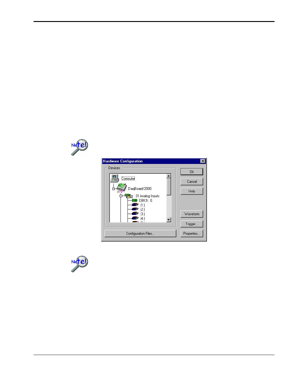
(c) Select the desired DBK module from the list provided. If DBK9 were selected we would end up
with a screen image similar to that shown in the following figure.
When adding a DBK module, the DBK modules must be added in sequential order
with no gaps.
Double-Clicking on the “DBK9: 0” will allow you to configure the card
All sub-addresses of a base system channel must be occupied,
regardless of whether or not a DBK is actually present. If this is not
performed, the program will not properly handle communication with
cards on higher address numbers.
For example, when using a DBK9, an 8-channel card, you must select
“2” as the number of devices,
even if you are using only one DBK9
.
(See following figure).
A single icon handles all cards within the same base address so you need to
exercise care in matching the icon software channel to the hardware sub-
address and channel.