Clock settings …… b-8 – Measurement Computing DASYLab User Manual
Page 62
B-8 Configuring DASYLab for Daq Devices
989593
DASYLab – Standard Driver
Hardware Level Trigger Details
:
For “True” oscilloscope simulation, software triggering with DASYLab modules is
recommended, as opposed to hardware triggering.
Note: Hardware triggering is only meaningful when in Series Mode.
• The first channel in the scan list is used (i.e. lowest channel number; main unit = 0-15,
DBK on 0 = 16-31, DBK on 1 = 32-47, etc.)
• DBK7, DBK9, DBK19, DBK42, DBK44, DBK52 excluded.
• Voltage level must equal actual voltage input, not sensor units.
Note: DASYLab modules can also be used to set up software triggers of an infinite variety.
You can set the trigger event to start a continuous measurement, or to perform one conversion for
each channel.
¾
When waiting for a hardware trigger DASYLab will appear frozen until the trigger
event occurs.
¾
Trigger settings are saved in the Configuration File, but not with the worksheet.
DaqBoards and DaqBooks support the following trigger events:
• Immediate
• TTL edge
• Voltage Level on 1st (lowest) channel in scan
In regard to Voltage Level, on 1st (lowest) channel in scan:
◊ TCs and RTDs are excluded.
◊ The value of the Voltage Level entered must be analog.
◊ During measurement, signals from the first activated DASYLab channel will be compared to the
entered analog value.
◊ If the signal value rises above [or falls below] the entered analog value, a trigger event occurs.
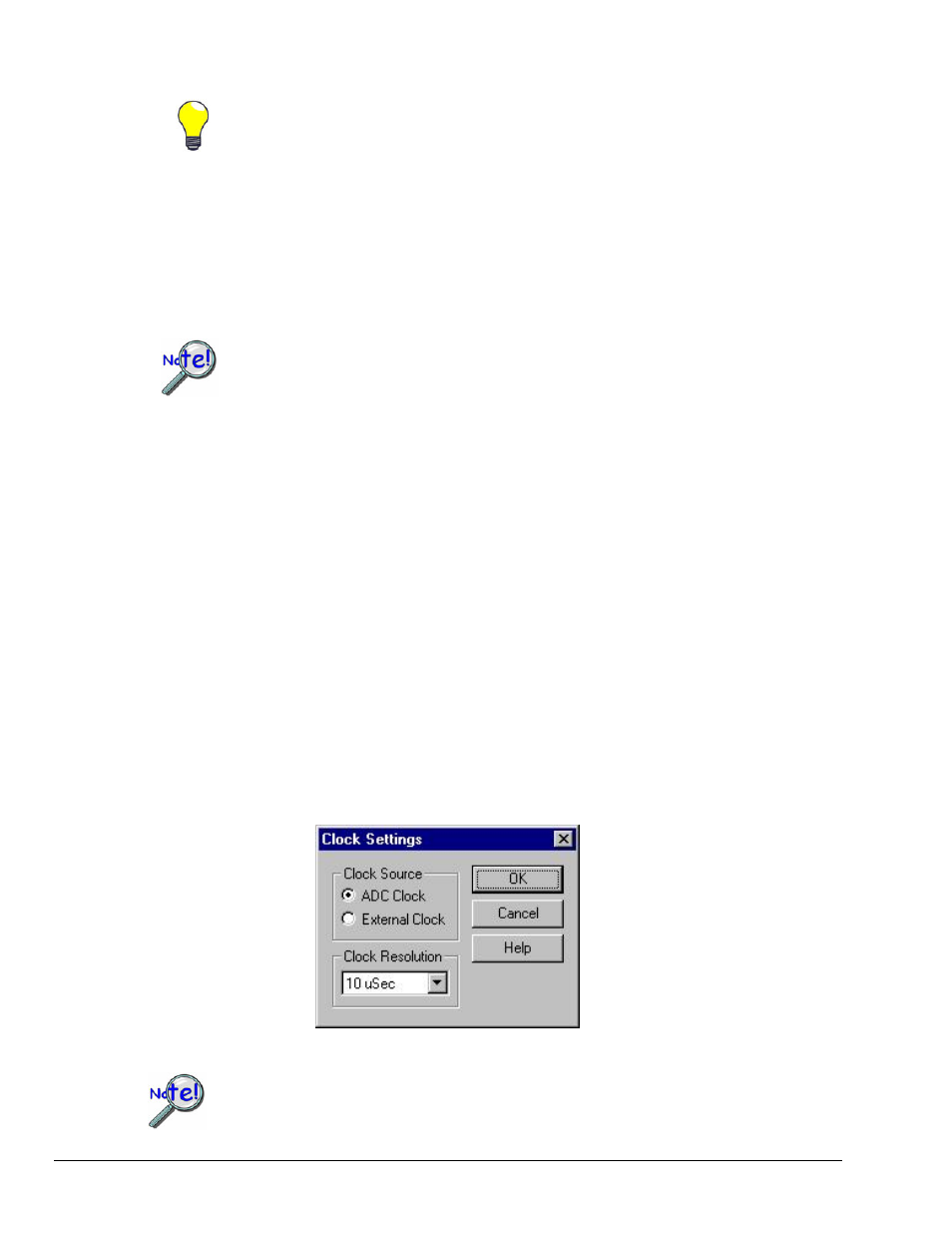
Clock Settings
When applicable, the Clock Settings control allows users to select desired timing option.
• the External Clock on P1 can be selected, or
• the A/D settle time can be changed.
Clock Settings
Clock settings are saved in the Configuration File, but not with the worksheet.