10 configuration tables – Measurement Computing CB-COM-7021 User Manual
Page 22
22
CB-7021, CB-7022, CB-7024 User’s Manual
e
d
o
C
3
0
4
0
5
0
6
0
7
0
8
0
9
0
A
0
e
t
a
r
d
u
a
B
0
0
2
1
0
0
4
2
0
0
8
4
0
0
6
9
0
0
2
9
1
0
0
4
8
3
0
0
6
7
5
0
0
2
5
1
1
7
6
5
4
3
2
1
0
0
1
*
2
*
3
*
e
d
o
C
e
p
y
T
0
3
1
3
2
3
3
3
4
3
5
3
F
3
t
u
p
t
u
O
.
n
i
M
A
m
0
V
m
4
V
0
V
0
1
-
V
0
V
5
-
-
t
u
p
t
u
O
.
x
a
M
A
m
0
2
A
m
0
2
V
0
1
+
V
0
1
+
V
5
+
V
5
+
-
e
t
o
N
4
2
/
P
1
2
/
1
2
0
7
-
I
r
o
F
y
l
n
o
4
2
0
7
-
I
r
o
F
2
2
0
7
-
I
r
o
F
y
l
n
o
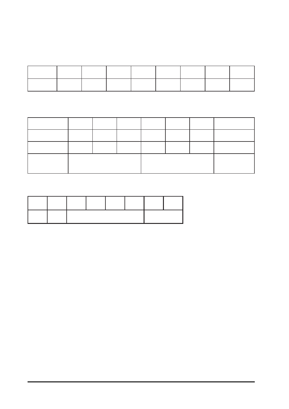
1.10 Configuration Tables
Baud rate Setting (CC)
Analog Output Type Setting (TT)
Data Format Setting (FF)
*1: Checksum Bit: 0=Disable, 1=Enable
*2: Slew Rate Control:
for CB-7021/21P and CB-7024, Refer Sec. 3.6 for de-
tails
for CB-7022, set to 0
*3: 00 = Engineering Unit Format
01 = Percent of Span Format (For CB-7021/21P/22)
10 = Hexadecimal Format (For CB-7021/21P/22)
This manual is related to the following products: