AMETEK Ls Series User Manual
Page 87
User Manual
Lx / Ls Series
83
phase configuration, press the Phase key until all phase enunciators (øA, øB and øC) are lit.
Waveform selections made in this mode will apply to all three phases.
4.4.3 Creating Custom Waveforms
The Lx controller supports up to 50 user defined waveforms in addition to the 3 standard
waveforms. Custom waveforms cannot be created from the front panel of the Lx Series. Rather,
they have to be downloaded through the IEEE-488 or RS232C interface.
Each waveform is defined by 1024 data points. Each data point can range between
–1 and +1
(floating point number). See Lx Series programming Manual (P/N 7004-961) for details on
downloading waveforms.
Once downloaded, waveforms remain in non-volatile memory and will be visible in the
WAVEFORMS menu for selection. The user can assign a 12-character name to each custom
waveform. Avoid using any of the standard waveform names (SINE, SQUARE or CLIPPED) as
these names will not be accepted.
Waveforms may be deleted using the IEEE-488 or RS232C interface as well. Custom waveforms
cannot be deleted from the front panel however to avoid accidental erasure.
4.4.4 RMS Amplitude Restrictions
The output of a sine wave may be programmed to the full rms value of the voltage range
selected. If the AC source is in the 300 V range, the maximum programmable rms voltage is 300
Volt. If a custom waveform is used however, the maximum programmable rms voltage may be
less than the maximum range value. The voltage range limit is based on the use of a sine wave
with a 1.414 crest factor. A 300 V rms sine wave has a 424 Volt peak voltage. The AC source
has a maximum peak voltage capability that is determined by the selected voltage range. If the
user selects a custom waveform with a crest factor that is higher than 1.414, the peak voltage
would exceed this maximum if the rms voltage were to be programmed at 300 V rms.
The Lx Series power source automatically limits the maximum allowable programmed rms
voltage of a any custom waveform by calculating the crest factor of the selected waveform and
controlling the rms limit accordingly. Thus, each custom waveform may have a different
maximum rms value. The controller will prevent the user from programming the rms voltage
above this limit. If a value is entered in the PROGRAM menu
above this value, a “Voltage peak
error” message is generated.
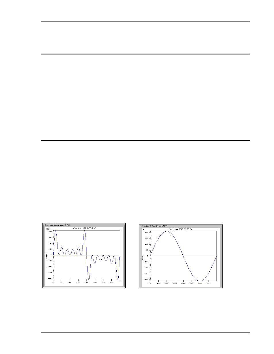
Figure 4-9: Waveform Crest Factor Affects Max. rms Voltage
The figure shown here illustrates the relationship between the crest factor of the wave shape (or
its “peakiness”) and the maximum peak voltage allowed for a given voltage range. Since the
peak voltage cannot exceed the AC source’s capabilities, the programmable rms voltage has to
be restricted, in this case to only 167.8785 volt for the waveform on the left. The sine wave on the