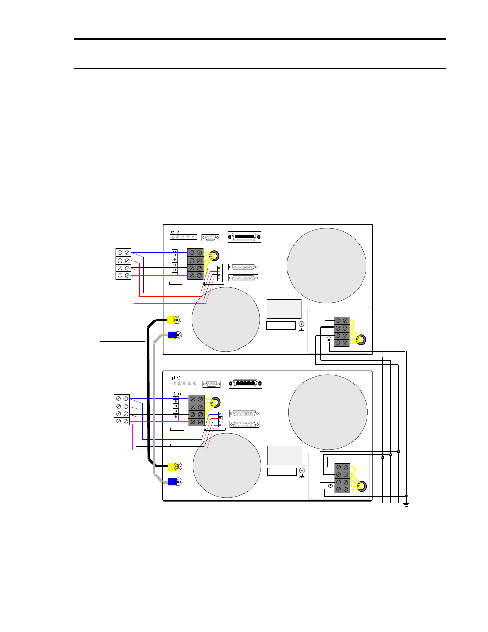
Er to figure 3-6, Figure 3-6: clock and lock connections, Ø1 ø2 ø3 com – AMETEK Ls Series User Manual
Page 57
User Manual
Lx / Ls Series
53
3.9.3 Lx versus Ls Differences
The Lx and Ls Series differ in how to control the phase angle of phase 1/A. On the Ls series,
setting the phase angle for phase A on the auxiliary unit will result in all three phases of the
auxiliary unit shifting by the same amount. Thus, programming the auxiliary unit to 60° on phase
A will result in a 60 degree offset between the two phase A outputs, B outputs and C outputs.
On the Lx Series, programming phase 1 of the auxiliary unit does not rotate phase B and C on
the auxiliary unit as well. There are two ways to accomplish this:
1. Program all three phases on the auxiliary unit with the same phase offset. Eg. Program
phase 1 to 60°, phase 2 to 300° and phase 3 to 180°.
2. Set the phase 1/A offset calibration coefficient for phase 1/A to the desired offset. This
will rotate all three phases, similar to setting the phase A angle on the Ls Series.
This discrepancy is caused by the requirement to maintain backward compatibility with the
HP6834B, which did not support Clock and Lock capability.
FLT INH OUT1 IN1 RPV
TRIGGER
IEEE-488
RS232C
AUX OUTPUT OUTPUT
HI
LO
HI
LO
26VAC
5VAC
Ø1
Ø2
Ø3
COM
SENSE
Ø1
Ø2
Ø3
COM
300 VAC MAX TO
TO MASTER INTERFACE
TO AUXILIARY INTERFACE
CLOCK
LOCK
FLT INH OUT1 IN1 RPV
TRIGGER
RS232C
AUX OUTPUT OUTPUT
HI
LO
HI
LO
26VAC
5VAC
Ø1
Ø2
Ø3
COM
SENSE
Ø1
Ø2
Ø3
COM
300 VAC MAX TO
TO MASTER INTERFACE
TO AUXILIARY INTERFACE
CLOCK
LOCK
EUT1
TERMINAL
BLOCK
LOAD
CLL/LK
MASTER
(-LKM)
CLK/LK
AUXILIARY
(-LKS)
L1 L2 L3 GND
AC SERVICE
ø1
ø2
ø3
COM
SERIAL TAG
L1
L2
L3
INPUT
INPUT
SAFETY
COVER
VOLTAGE INPUT
RATING
SERIAL TAG
L1
L2
L3
INPUT
INPUT
SAFETY
COVER
VOLTAGE INPUT
RATING
EUT2
TERMINAL
BLOCK
LOAD
ø1
ø2
ø3
COM
300 VAC MAX TO
CLK/LK
BNC
CABLES
WARNING:
DO NOT CONNECT
OUTPUTS OF
-LKM & -LKS UNITS
TOGETHER
Figure 3-6: Clock and Lock Connections