Ø1 ø2 ø3 com – AMETEK Ls Series User Manual
Page 45
User Manual
Lx / Ls Series
41
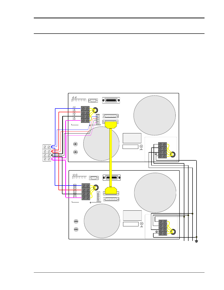
3.5.3 Multi-chassis Output Wiring Diagram
Figure 3-3 shows the required output connections for a 9000Lx/2 or 9000Ls/2 two chassis
system (rear-view perspective). Always turn off AC mains power to the 9000Lx/2 or 9000Ls/2
by turning off the circuit breakers on both the Master and Auxiliary 4500Lx / Ls power
source before making or changing output connections. The terminal block shown to connect
the outputs of both chassis together is provided in the 9000Lx/2 or 9000Ls/2 ship kit. The System
Interface cable is a DB25 to DB25 M/F cable approximately 2 meters in length. (CI P/N 250778).
This cable connects between the male DB25 connector on the Master unit rear panel labeled TO
AUXILIARY INTERFACE and the female DB25 connector on the Auxiliary unit rear panel labeled
TO MASTER INTERFACE as shown in Figure 3-3. The OUTPUT SAFETY COVER must be
removed to use the System Interface and the AC Source must be installed in a cabinet with a
protective rear screen or door.
FLT INH OUT1 IN1 RPV
TRIGGER
IEEE-488
RS232C
AUX OUTPUT OUTPUT
HI
LO
HI
LO
26VAC
5VAC
Ø1
Ø2
Ø3
COM
SENSE
Ø1
Ø2
Ø3
COM
300 VAC MAX TO
TO MASTER INTERFACE
TO AUXILIARY INTERFACE
CLOCK
LOCK
FLT INH OUT1 IN1 RPV
TRIGGER
RS232C
AUX OUTPUT OUTPUT
HI
LO
HI
LO
26VAC
5VAC
Ø1
Ø2
Ø3
COM
SENSE
Ø1
Ø2
Ø3
COM
300 VAC MAX TO
TO MASTER INTERFACE
TO AUXILIARY INTERFACE
CLOCK
LOCK
9000Lx/2
TERMINAL
BLOCK
LOAD
MASTER
AUXILIARY
L1 L2 L3 GND
AC SERVICE
ø1
ø2
ø3
COM
SERIAL TAG
L1
L2
L3
INPUT
INPUT
SAFETY
COVER
VOLTAGE INPUT
RATING
SERIAL TAG
L1
L2
L3
INPUT
INPUT
SAFETY
COVER
VOLTAGE INPUT
RATING
Figure 3-3: 9000Lx/2 and 9000Ls/2 Output Wiring