3 measurement calibration – AMETEK Ls Series User Manual
Page 100
User Manual
Lx / Ls Series
96
6.3 Measurement Calibration
The Lx/Ls Series controller measures voltage and current by digitizing both voltage and current
waveforms on each available output phase. This data is subsequently processed and use to
calculate all measurement parameters such as VRMS, IRMS, Power, VA, Frequency etc. To
calibrate all measurements, only the voltage and current measurement need to be calibrated
specifically. All other measurements are derived from these.
Connect the test equipment to the power source. If the power system is a master/auxiliary multi-
box system with one controller, the DVM for calibrating the measurement voltage should always
be connected to the Remote Sense connector on the Master cabinet.
Note: The Fluke 8506A or Agilent HP 34401A Digital Multi meter (or higher AC accuracy
DMM) must be used for the following calibration. The DMM must be set to the AC
HI ACCUR mode for all AC measurements.
The shunt must be connected in series with the load. Connect the load to the output. Use a 10
mOhm current shunt of sufficient power rating in series with the load to measure the AC load
current.
To calibrate all measurement functions, the desired value for the measurement value of current
or voltage must be entered for the corresponding calibration value. Make the indicated
adjustments by typing in the desired display value. This should be the value indicated by the
external DVM. If a 10 mOhm current shunt is used for current, 300 mV represents 30 amps.
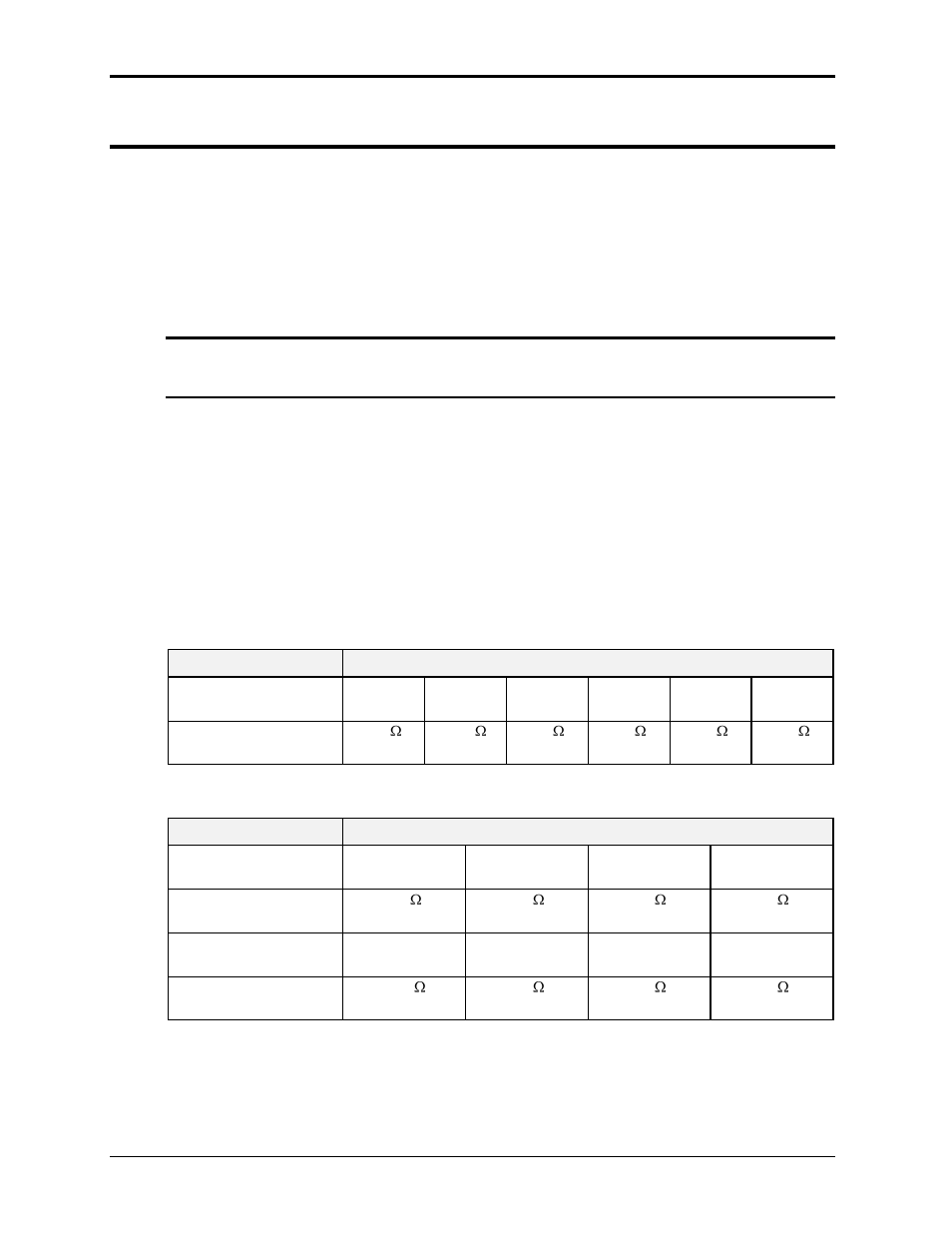
The Calibration Load Table shows required load bank settings for the current measurement
calibration procedure. The current should be calibrated in the lowest voltage range only. (Highest
current range). The current measurement calibration must be performed for Phase A in both
single and three phase mode and for phase B and C in three phase mode only.
PARAMETER
POWER SYSTEM
Model --->
3000Lx
1 Phs
3000Lx
3 Phs
4500Lx
1 Phs
4500Lx
3 Phs
6000Lx
1 Phs
6000Lx
3 Phs
Max current, 120 V, Lo
Vrange
4.8
3 kW
14.4
1 kW
3.2
4.5 kW
9.6
1.5 kW
2.4
6 kW
7.2
6 kW
Table 6-1: Calibration Load Values- Single-chassis configurations
PARAMETER
POWER SYSTEM
Model --->
9000Lx/2
1 phs mode
9000Lx/2
3 phs mode
12000Lx/2
1 phs mode
12000Lx/2
3 phs mode
Max current, 120 V, Lo
Vrange
1.6
9 kW
4.8
3 kW
1.2
12 kW
3.6
4 kW
Model --->
13500Lx/3
1 phs mode
13500Lx/3
3 phs mode
18000Lx/2
1 phs mode
18000Lx/3
3 phs mode
Max current, 120 V, Lo
Vrange
0.96
13.5 kW
3.2
4.5 kW
0.8
18 kW
7.2
6 kW
Table 6-2: Calibration Load Values- Multi-chassis configurations