AMETEK Ls Series User Manual
Page 86
User Manual
Lx / Ls Series
82
4.4 Waveform Management
The Lx Series employs independent arbitrary waveform generators for each phase. This allows
the user to create custom waveforms. In addition, three standard waveforms are always
available. This chapter covers issues that relate to defining, downloading and managing custom
waveforms.
Ls Series model only support arbitrary waveform generation if the
–ADV option is installed. If not,
you can skip forward to section 4.5 as the next sections do not apply.
4.4.1 Standard Waveforms
For most AC applications, a sine wave shape is used. The sine wave is one of the standard
waveforms provided on all Lx Series models. This standard sine wave is always available and is
the default waveform at power-on. Two more standard waveforms are available, square and
clipped.
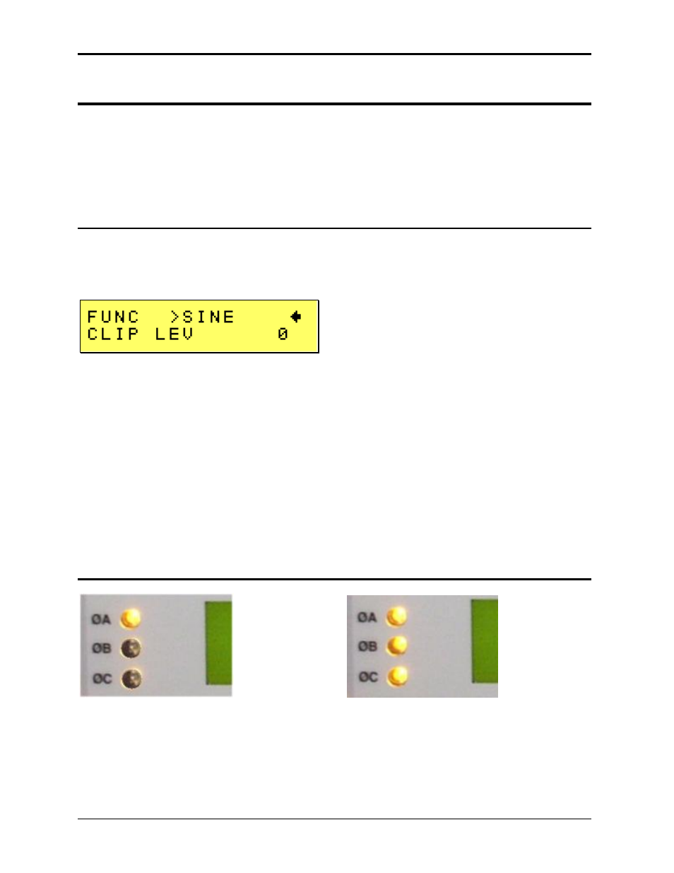
Figure 4-7: Selecting a Waveform
The square wave provides a high frequency content waveform with relative fast rise and fall
times. Due to AC amplifier bandwidth limitations, the frequency content of the standard square
wave has been kept within the amplifier’s capabilities. As the fundamental frequency is
increased, the relative contribution of higher harmonics is reduced.
The clipped sine wave may be used to simulate voltage distortion levels to the unit under test.
The total harmonic distortion level may be programmed in percent using the CLIP LEV field
directly below the FUNC entry.
Note that changing the distortion level of the clipped waveform forces the AC source to
regenerate the clipped s
ine wave’s data points and reload the waveform register with the newly
requested data. This process requires the output to be dropped briefly. To avoid interrupting the
voltage output to the unit under test, set the clip level needed before closing the output relay and
do not change it while the EUT is under power. You can then toggle between the clipped sine
wave and any other waveform in memory without interrupting the output.
4.4.2 Phase Selection
Figure 4-8: Selecting Waveforms for Single Phase or All Phases
Different waveforms may be selected for each phase. The number of custom waveforms from
which to select remains 50 but each phase can be assigned a different custom or standard
waveform. The specific output phase for which the wave shape is programmed is selected with
the Phase key on the front panel. To select the same wave shape for all three phases in a three-