AMETEK Ls Series User Manual
Page 44
User Manual
Lx / Ls Series
40
3.5.2 Output Terminal Block - OUTPUT
Each 3000/4500/6000Lx\Ls chassis has a single AC output terminal block. For tabletop operation
of a single chassis system, the output terminal block must be covered using the supplied AC
Output safety cover. The terminal blocks are large enough to accommodate required wire gauge
sizes. The terminal block is located in the upper left corner on the rear panel of the unit. (Looking
from the back).
Multi-chassis configurations have two or more output terminal blocks, one on the master Lx \ Ls
chassis and one of the auxiliary Lx \ Ls chassis.
For operation as a multi-chassis system, the outputs of all Lx \
Ls chassis’ must be connected
together using the additional terminal blocks provided in the Lx \ Ls ship kit. Keep the wire
lengths between each chassis and this common terminal block the same.
See Figure 3-3 for output wiring diagram.
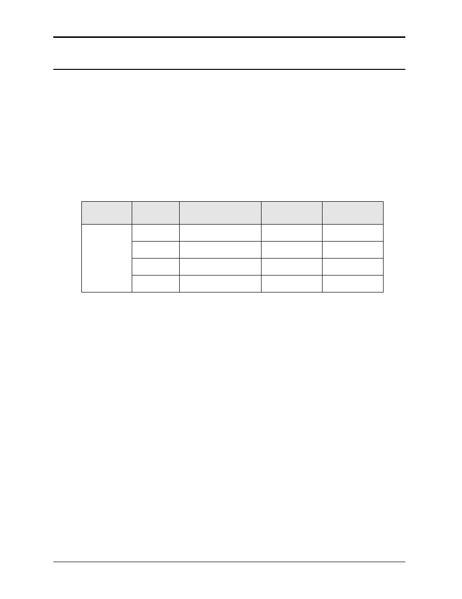
Connector
Terminal
Mode
Lx Output
OUTPUT
Ls Output
TB1
1
3 Phase & 1 Phase
Ø1
ØA
2
3 Phase
Ø2
ØB
3
3 Phase
Ø3
ØB
4
Common / Neutral
COM
NEUT
Table 3-1: Output Terminal connections.