Table 3-7, Table 3-8, Table 3-6 – AMETEK Ls Series User Manual
Page 51
User Manual
Lx / Ls Series
47
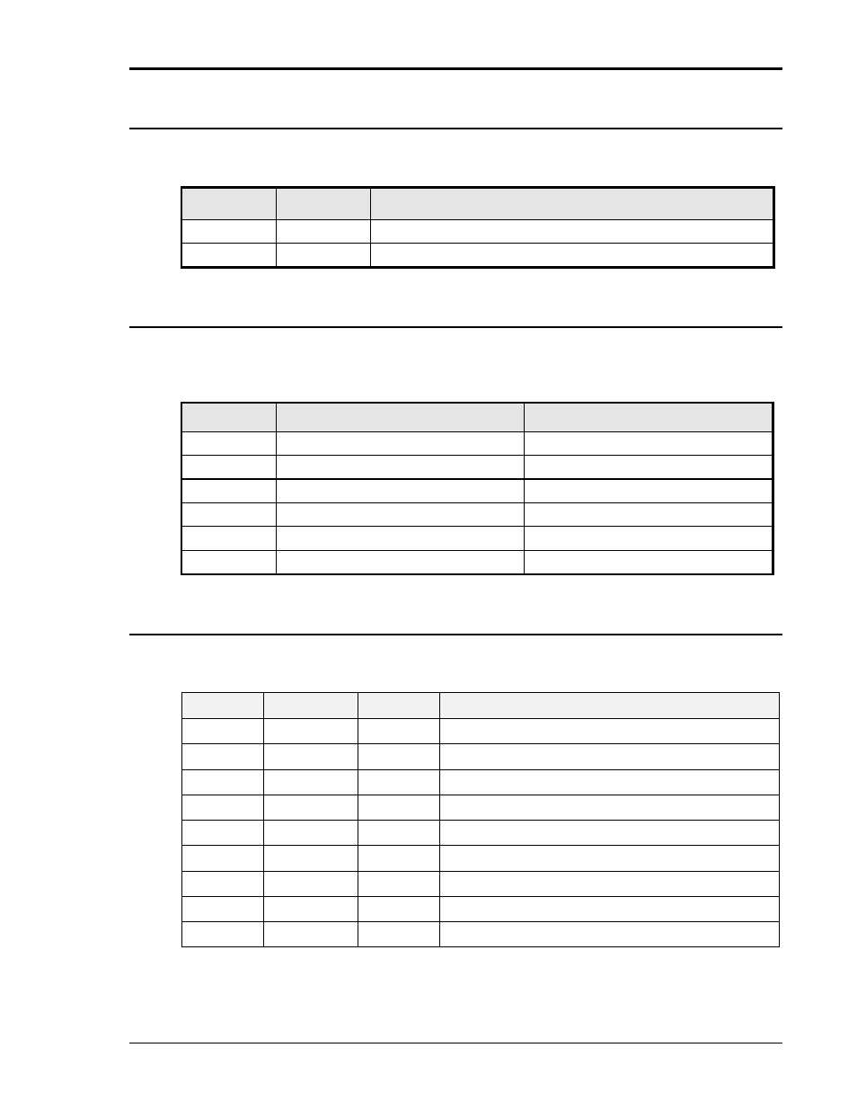
3.6.4 BNC Connectors (-LKM / -LKS options)
BNC connectors. Functions are called out on rear panel decal. Table 3-6 shows connections for
the optional -LKM and -LKS clock and lock mode. Refer to section 3.9 for more details.
BNC
Ls Series
Ref.
Description
CLOCK
J1
Clock Option (TTL output on Master / TTL input on Auxiliary) N/A
LOCK
J2
Lock Option (TTL output on Master / TTL input on Auxiliary) N/A
Table 3-6: BNC Connectors
3.6.5 External Sense Connector
– SENSE
The external sense connections for Phase 1, 2 and 3 (A, B and C) in three-phase mode and
Phase 1 (A) in single phase mode MUST be connected for correct operation. Sense connections
must be made at the MASTER 4500Lx/Ls unit for a multi-box Lx/Ls system.
Pin
Description - Lx Series
Description - Ls Series
1
Phase 1 sense Hi
Phase A sense Hi
2
Phase 2 sense Hi
Phase B sense Hi
3
Phase 3 sense Hi
Phase C sense Hi
4
Neutral sense
Neutral sense
5
-AX Option Phase D Hi
– N/A
-AX Option Phase D Hi
– N/A
6
-AX Option Phase D Lo
– N/A
-AX Option Phase D Lo
– N/A
Table 3-7: External Sense Connector
3.6.6 RS232C Serial Interface
– RS232C
A standard RS232C DB9 connector is located on the rear panel for serial control. A straight thru
DB9 male to DB9 female interface cable to 9-pin PC serial port connector may be used
Pin
Designator
Dir.
Description
1
Not used
N/C
2
TxD
Output
Transmit data
3
RxD
Input
Receive data
4
Not used
N/C
5
Common
Common
6
Not used
N/C
7
CTS
Input
Clear to send
8
RTS
Output
Request to send
9
Not used
N/C
Table 3-8: RS232C Connector