6 available options – lx series – AMETEK Ls Series User Manual
Page 28
User Manual
Lx / Ls Series
24
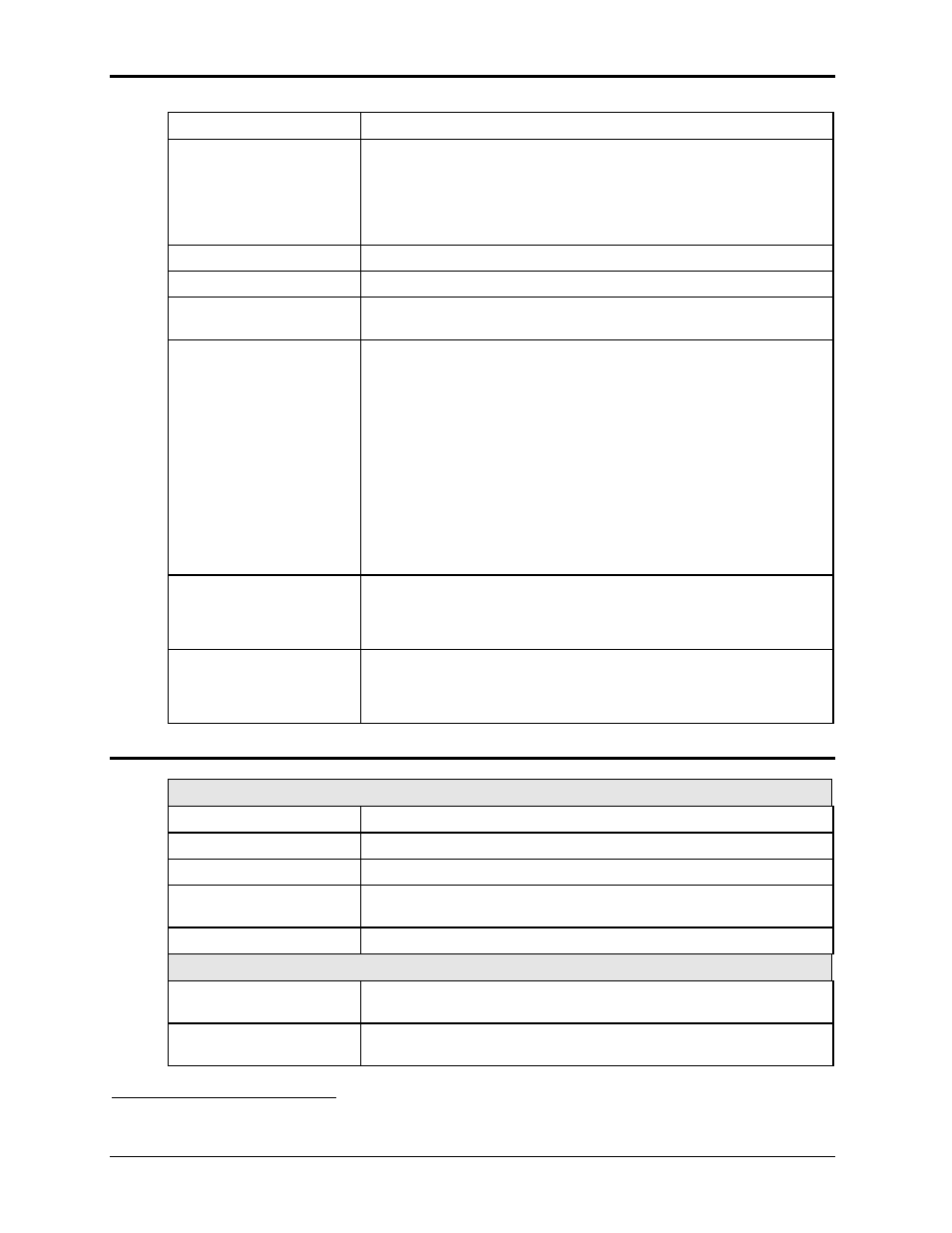
Mode:
Switches between 1 and 3 phase outputs.
Parallel Operation:
9000Lx/2 and 13500Lx/2 systems use two or three 4500Lx chassis in
parallel operation. The two or three chassis must be connected using the
system interface cable supplied with the system.
12000Lx/3 and 18000Lx/3 systems use two or three 6000Lx chassis in
parallel operation. The two or three chassis must be connected using the
system interface cable supplied with the system
Controller:
Programmable controller front panel assembly.
Output Relay:
Standard output relay feature to isolate power source from the load.
Output On/Off:
The output relay can be used to quickly disconnect the load. A yellow
status indicator displays the status of the output relay.
External Trigger Output
or Function Strobe
An external TTL output is available which may be used to trigger other
equipment. The TTL output can be controlled by the transient
programming system. This requires the trigger mode to be set to EXT
(factory default). This can only be done over the bus using the
OUTP:TTLT:MODE TRIG command. This mode is compatible with the
Agilent HP6834B.
It can also be configured to generate an output pulse any time the
voltage, frequency, current limit or phase programming is updated. This
requires the trigger mode to be set to FSTR. This can only be done over
the bus using the OUTP:TTLT:MODE FSTR command. This mode is
compatible with the CI L Series.
The Trigger Output (Trig Out1) / function strobe is an active low
1
TTL
signal with a duration of no less than 400 usec.
Clock and Lock Mode
Enables two or more independent Ls/Lx power systems to be phase
synchronized to each other. One system (-LKM) acts as the master, the
other(s) (-LKS) as auxiliaries. The
–LKS units are synced to the –LKM
unit. Refer to section 3.9 for details on Clock and Lock mode.
Trigger Input
A TTL input signal may be used as an external trigger source for output
changes programmed on the AC power source transient system. This
requires the trigger source to be set to EXT. This can only be done over
the bus.
2.6 Available Options
– Lx Series
Output Options
-AX
Auxiliary outputs, 5 VAC and 26 VAC, 400 Hz. (Output D and E)
- HV
135 / 270 V range output
- EHV
200 / 400 V range output
-HF
High frequency option. Increases output frequency to 5000 Hz (single
chassis configurations) or 2000 Hz (multi-chassis models).
-LF
Low frequency option. Limits maximum output frequency to 500 Hz.
Firmware Options
- 704
Mil Std 704 test firmware.
Includes AC tests for Revisions D and E
- 704F
Mil Std 704 test firmware.
Includes AC tests for Revisions A through F
1 Note: Early production models may have an active high Trig Out1 polarity.