Security key and battery backup, Security key and battery backup –69 – Altera Stratix III Development Board User Manual
Page 77
Chapter 2: Board Components
2–69
Power Supply
May 2013
Altera Corporation
Stratix III 3SL150 Development Board
Reference Manual
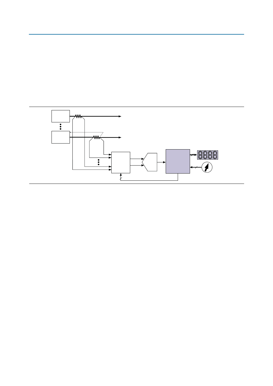
This capability is realized using a 32-channel analog multiplexer to a 2-channel
differential A/D converter, with a digital data bus connected to the MAX II CPLD.
The CPLD contains a logic design that continually monitors the rails and displays the
current in mA on the dedicated four-digit, 7-segment display or graphics display.
Because only a single rail can be displayed at any time on the 7-segment display, an
octal rotary switch is used to select which rail is currently being displayed. The sense
resistor is large enough that it can be easily probed to confirm the display results. To
see all of the currents at the same time, you can use the graphics display.
illustrates the circuit.
Security Key and Battery Backup
Stratix III devices are protected against copying, reverse engineering, and tampering
using configuration bit-stream encryption. Specifically, the Stratix III devices use an
advanced encryption standard (AES) algorithm with a 256-bit user-generated key. The
key is stored on the Stratix III device and is used to decrypt the incoming
configuration data bit-stream before configuration and initialization can begin.
This section discusses the following two methods of storing Stratix III device’s 256-bit
encryption key:
■
Volatile
■
Non-volatile
In the volatile scheme, the 256-bit key itself can be reprogrammed as needed. In this
case, a 2.5-V battery is required to power the V
CCBAT
input and maintain the key
within the Stratix III device when the system is powered off.
In the non-volatile scheme, the 256-bit key is programmed once into the Stratix III
device and cannot be changed. The advantage of the non-volatile scheme is that a
battery is not required to power the V
CCBAT
input.
By providing a 2.5-V coin battery connected to the V
CCBAT
power input, the board
provides support for both volatile and non-volatile keys. A battery socket is also
provided to allow battery replacement as needed. Additionally, the V
CCBAT
power
input has a jumper to allow the VCCBAT pin to be tied directly to GND when the
battery is removed for supporting the non-volatile key mode.
Figure 2–21. Power Measurement System
MAX II Device
LTC2402
ADC
Load #1
Load #16
Supply #1
R SENSE
R SENSE
feedback
4-Digit Rail
Select
4-Digit
7-Segment or
OLED Display (mA)
Powered by Rail
1A
1B
16A
16B
ADG725
DA
DB
Supply #16
4
4