System reset and configuration switches, Power select rotary switch – Altera Stratix III Development Board User Manual
Page 31
Chapter 2: Board Components
2–23
Configuration, Status, and Setup Elements
May 2013
Altera Corporation
Stratix III 3SL150 Development Board
Reference Manual
System Reset and Configuration Switches
Board reference S7 is the system reset push-button switch, RESET_CONFIG, which is an
input to the MAX II device. This switch forces a reconfiguration of the FPGA from
flash memory. The location in flash memory is based on the input from the PGM
Config Select rotary switch position for the signals PGM [2:0]. The MAX II device uses
the RESET_CONFIGn pin as its reset along with the CPU_RESET pin push-button.
Board reference S6 is the CPU reset push-button switch, CPU_RESET, which is an input
to both the Stratix III FPGA and the MAX II CPLD. The CPU_RESET push-button is
intended to be the master reset signal for the FPGA design loaded in the Stratix III
device, and connects to a regular I/O pin on the FPGA. The MAX II device uses this
push-button as its reset along with the RESET_CONFIG and FACTORY_CONFIG push-
buttons.
Board reference S1 is the factory push-button, FACTORY_CONFIG, which is an input to
the MAX II device. The FACTORY_CONFIG pin forces a reconfiguration of the FPGA with
the factory default FPGA design, which is located at the base of flash memory. See
lists the push-button switch component reference and manufacturing
information.
For information about user-defined push-buttons, refer to
.
Power Select Rotary Switch
A 16-position rotary switch, board reference SW6, is used to select the current power
rail whose power is being measured and displayed on the power display. The rotary
switch is connected to the MAX II CPLD.
Upon first use, after configuring or powering up the board, make sure you initiate
changes to the rotary switch (SW6) so that the measurement circuit can initiate a
channel reading. Otherwise, the measurement might be reading a previous capture.
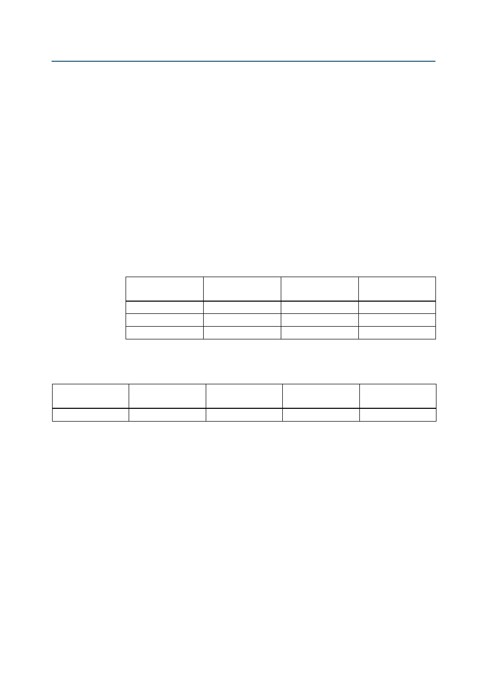
Table 2–14. Push-Button Switch Signal Name and Function
Board Reference
Schematic
Signal Name
Stratix III Device
Pin Number
MAX II Device
Pin Number
S1
FACTORY_CONFIG
—
A10
S7
RESET_CONFIGn
—
R16
S6
CPU_RESET
T21
M9
Table 2–15. Push-Button Switch Component Reference and Manufacturing Information
Board Reference
Description
Manufacturer
Manufacturing
Part Number
Manufacturer
Website
S1, S6, S7
Push-button switch
Panasonic
EVQAPAC07K