Convert sd bits, Insert sync bits, Convert sd bits -26 – Altera SDI II MegaCore User Manual
Page 68: Insert sync bits -26
Convert SD Bits
This submodule is enabled when you set the SD Interface Bit Width parameter option to 20. This
submodule converts the SD parallel data in 20 bits back to 10 bits format required for further processing.
This submodule contains a clock enable generator to generate two data valid pulses at every 11th clock
cycle of the
tx_pclk
domain. Each time the data valid signal is asserted, this block will alternately output
the lower 10 bits and upper 10 bits of the SD 20-bit interface data to the downstream logic.
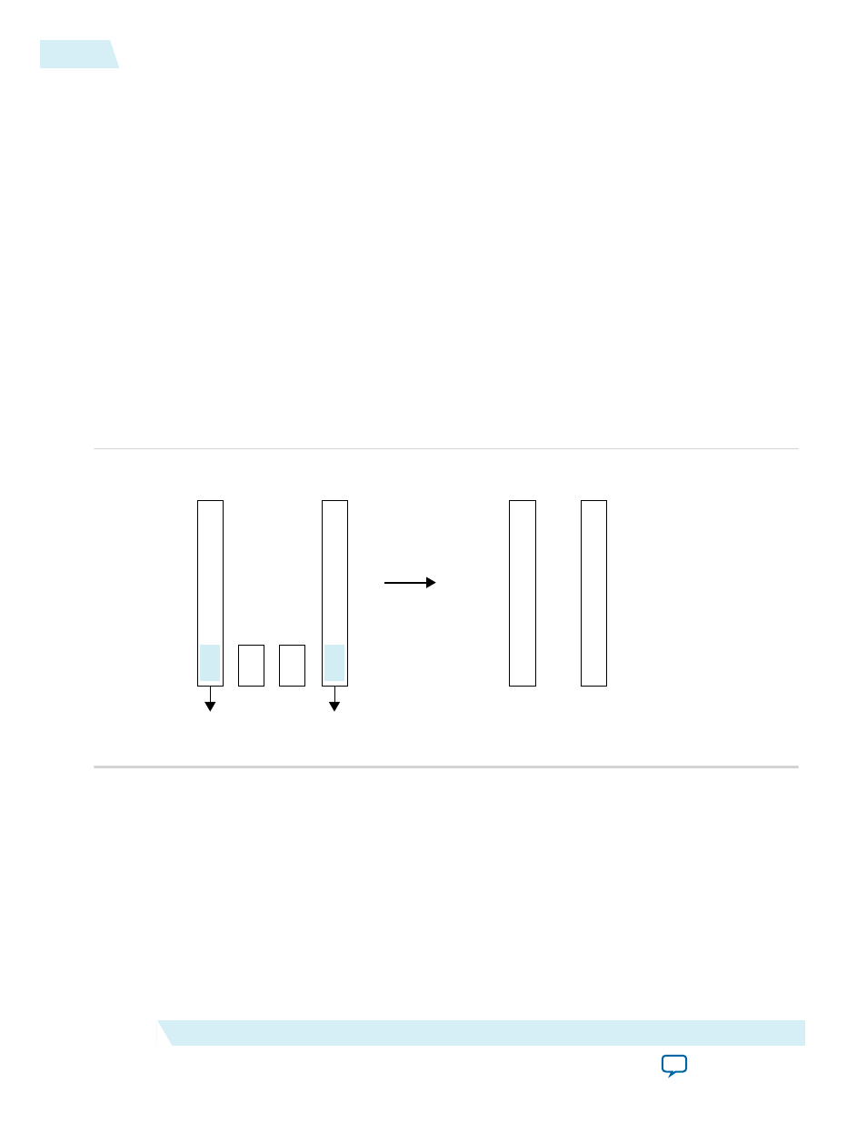
Insert Sync Bits
Inserting sync bits prevents long runs of zeroes.
Repeating patterns of 3FF or 000h for 6G-SDI and 12G-SDI video standards in the 10-bit parallel interface
may result in a long run of zeroes feeding the scrambling polynomial. A long run of zeroes goes up to a
length of 160 "1"s and 339 "0"s, which may cause the generation of the pothole pathological condition.
To prevent the long runs, this feature modifies the 10-bit parallel interface data stream. It replaces the two
LSBs of repeated 3FF or 000 code words with sync-bit values of 10b for 000h words and 01b for 3FFF
words.
Figure 4-22: Sync Bits
1
1
1
1
1
1
1
1
1
1
0
0
0
0
0
0
0
0
0
0
0
1
1
0
10-bit Word
3FFh
10-bit Word
000h
MSB
LSB
Two LSBs
Replaced with
10-bit Word
3FDh
10-bit Word
002h
1
1
1
1
1
1
1
1
0
1
0
0
0
0
0
0
0
0
1
0
10-bit Word
3FFh
10-bit Word
000h
MSB
LSB
TRS/AFD Preambles
after Sync Bit Insertion
However, to ensure the words are synchronized and aligned in the receiver, this feature retains one
complete sequence of preambles (3FFh 000h 000h) without modification.
4-26
Convert SD Bits
UG-01125
2015.05.04
Altera Corporation
SDI II IP Core Functional Description