Altera Integer Arithmetic IP User Manual
Page 60
N represents the number of cycles of data that has entered into the accumulator, y(t) represents the output
at time t, A(t) represents the input at time t, and B(i) are the coefficients. The t and i in the equation
correspond to a particular instant in time, so to compute the output sample y(t) at time t, a group of input
samples at N different points in time, or A(n), A(n-1), A(n-2), … A(n-N+1) is required. The group of N
input samples are multiplied by N coefficients and summed together to form the final result y.
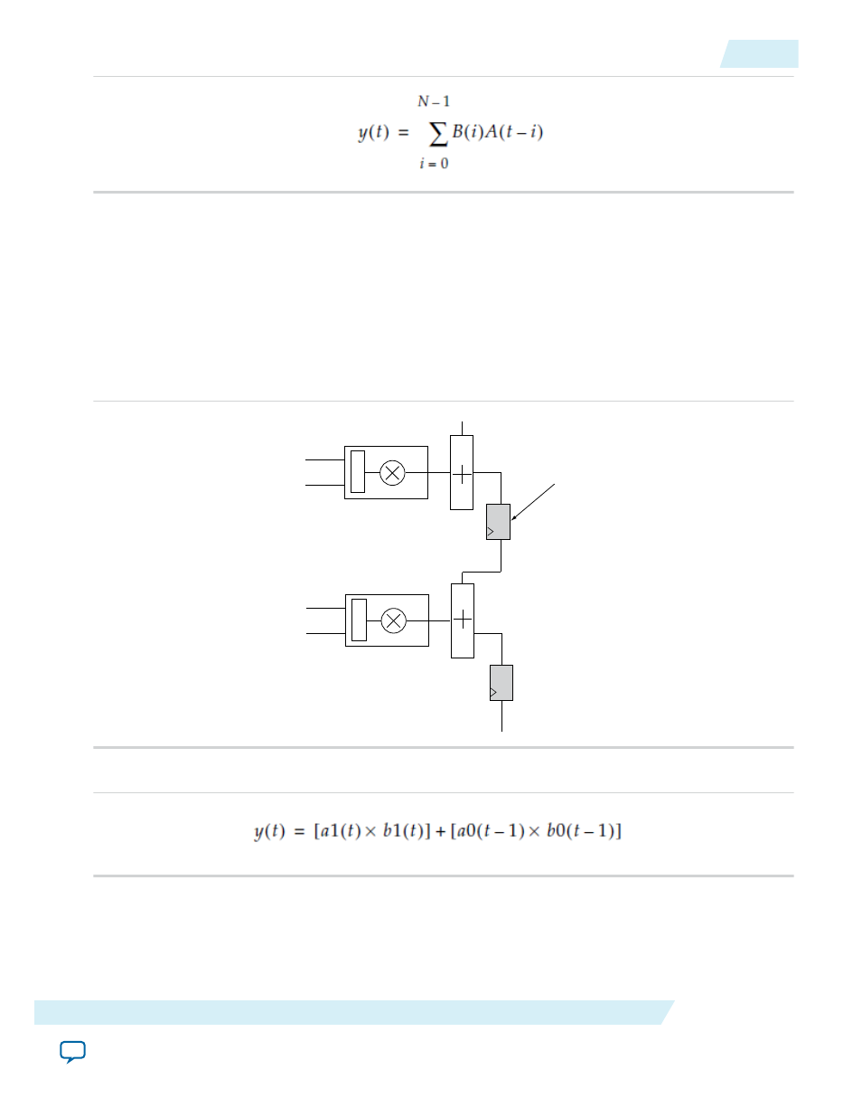
The systolic register architecture is available only for sum-of-2 and sum-of-4 modes.
The following figure shows the systolic delay register implementation of 2 multipliers.
Figure 6-8: Systolic Delay Register Implementation of 2 Multipliers
a0
b0
Mult0
result
chainin
a1
b1
Mult1
+/-
+/-
Systolic registers
The sum of two multipliers is expressed in the following equation.
The following figure shows the systolic delay register implementation of 4 multipliers.
UG-01063
2014.12.19
Systolic Delay Register
6-7
ALTERA_MULT_ADD (Multiply-Adder)
Altera Corporation