Resource utilization and performance, Verilog hdl prototype, Vhdl component declaration – Altera Integer Arithmetic IP User Manual
Page 112: Resource utilization and performance -11, Verilog hdl prototype -11, Vhdl component declaration -11
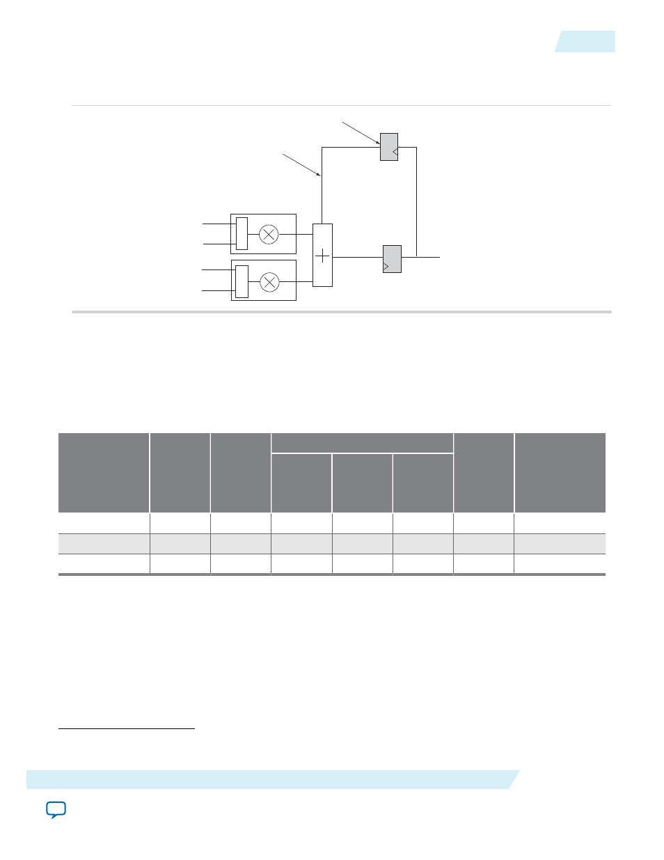
The following figure shows the double accumulator implementation.
Figure 9-12: Double Accumulator
a0
b0
a1
b1
Mult0
Mult1
Accu mulator feedba ck
Output result
+/-
+/-
Dou ble Accu mulator Register
Output Register
Resource Utilization and Performance
The following table provides resource utilization and performance information for the ALTMULT_ADD
megafunction.
Table 9-1: ALTMULT_ADD Resource Utilization and Performance
Device family
Input data
width
Output
latency
Logic Usage
18-bit DSP
f
MAX
(MHz)
(6)
Adaptive
Look-Up
Table
(ALUT)
Dedicated
Logic
Register
(DLR)
Adaptive
Logic
Module
(ALM)
Stratix III
16 x 16
3
0
0
0
2
645
32 x 32
3
0
0
0
4
454
64 x 64
3
217
128
146
16
145
Verilog HDL Prototype
To view the Verilog HDL prototype for the megafunction, refer to the Verilog Design File (.v) altera_mf.v
in the
directory.
VHDL Component Declaration
(6)
The performance of the megafunction is dependant on the value of the maximum allowable ceiling f
MAX
that the selected device can achieve. Therefore, results may vary from the numbers stated in this column.
UG-01063
2014.12.19
Resource Utilization and Performance
9-11
ALTMULT_ADD (Multiply-Adder)
Altera Corporation