Verilog hdl prototype, Vhdl component declaration, Verilog hdl prototype -2 – Altera Integer Arithmetic IP User Manual
Page 152: Vhdl component declaration -2
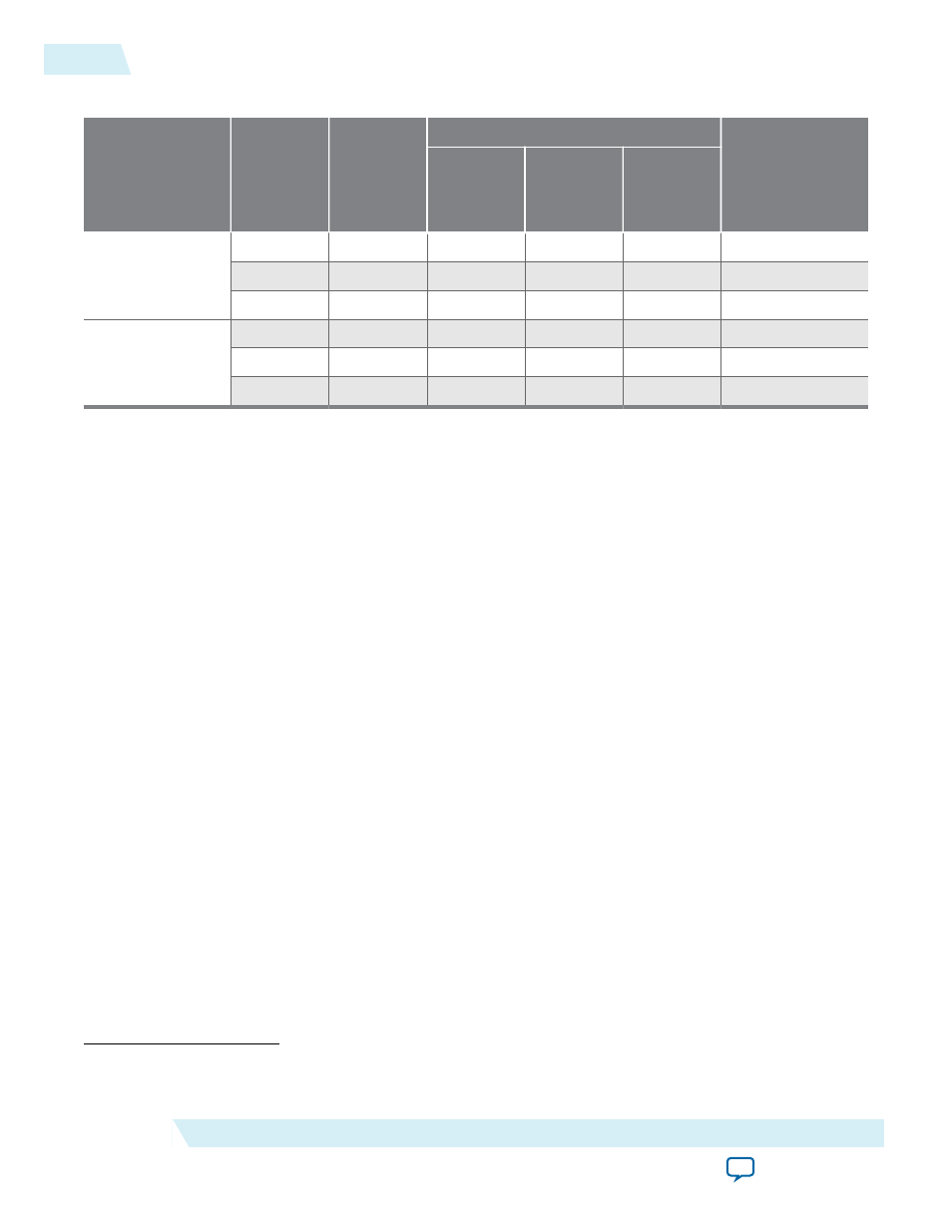
Table 12-1: PARALLEL_ADD Resource Utilization and Performance
Device family
Input data
width
Output
latency
Logic Usage
f
MAX
(MHz)
(9)
Adaptive
Look-Up
Table (ALUT)
Dedicated
Logic
Register
(DLR)
Adaptive
Logic
Module
(ALM)
Stratix III
8
1
40
0
21
793
32
5
142
0
102
378
64
10
283
0
189
280
Stratix IV
8
1
40
0
21
854
32
5
142
0
103
472
64
10
283
0
199
346
Verilog HDL Prototype
The following Verilog HDL prototype is located in the Verilog Design File (.v) altera_mf.v in the
module parallel_add (
data,
clock,
aclr,
clken,
result);
parameter width = 4;
parameter size = 2;
parameter widthr = 4;
parameter shift = 0;
parameter msw_subtract = "NO"; // or "YES"
parameter representation = "UNSIGNED";
parameter pipeline = 0;
parameter result_alignment = "LSB"; // or "MSB"
parameter lpm_type = "parallel_add";
input [width*size-1:0] data;
input clock;
input aclr;
input clken;
output [widthr-1:0] result;
endmodule
VHDL Component Declaration
(9)
The performance of the megafunction is dependant on the value of the maximum allowable ceiling f
MAX
that the selected device can achieve. Therefore, results may vary from the numbers stated in this column.
12-2
Verilog HDL Prototype
UG-01063
2014.12.19
Altera Corporation
PARALLEL_ADD (Parallel Adder)