Configuration error detection, User mode error detection, Error detection block – Altera MAX 10 FPGA User Manual
Page 23
Configuration Error Detection
In configuration mode, a frame-based CRC is stored in the configuration data and contains the CRC value
for each data frame.
During configuration, the MAX 10 device calculates the CRC value based on the frame of data that is
received and compares it against the frame CRC value in the data stream. Configuration continues until
the device detects an error or when all the values are calculated.
For MAX 10 devices, the CRC is computed by the Quartus II software and downloaded into the device as
part of the configuration bit stream. These devices store the CRC in the 32-bit storage register at the end
of the configuration mode.
User Mode Error Detection
SEUs are changes in a CRAM bit state due to an ionizing particle. MAX 10 devices have built-in error
detection circuitry to detect data corruption in the CRAM cells.
This error detection capability continuously computes the CRC of the configured CRAM bits. The CRC of
the contents of the device are compared with the pre-calculated CRC value obtained at the end of the
configuration. If the CRC values match, there is no error in the current configuration CRAM bits. The
process of error detection continues until the device is reset—by setting
nCONFIG
to low.
The error detection circuitry in MAX 10 device uses a 32-bit CRC IEEE Std. 802 and a 32-bit polynomial
as the CRC generator. Therefore, the device performs a single 32-bit CRC calculation. If an SEU does not
occur, the resulting 32-bit signature value is
0x000000
, which results in a
0
on the output signal
CRC_ERROR
. If an SEU occurs in the device, the resulting signature value is non-zero and the
CRC_ERROR
output signal is
1
. You must decide whether to reconfigure the FPGA by strobing the
nCONFIG
pin low or
ignore the error.
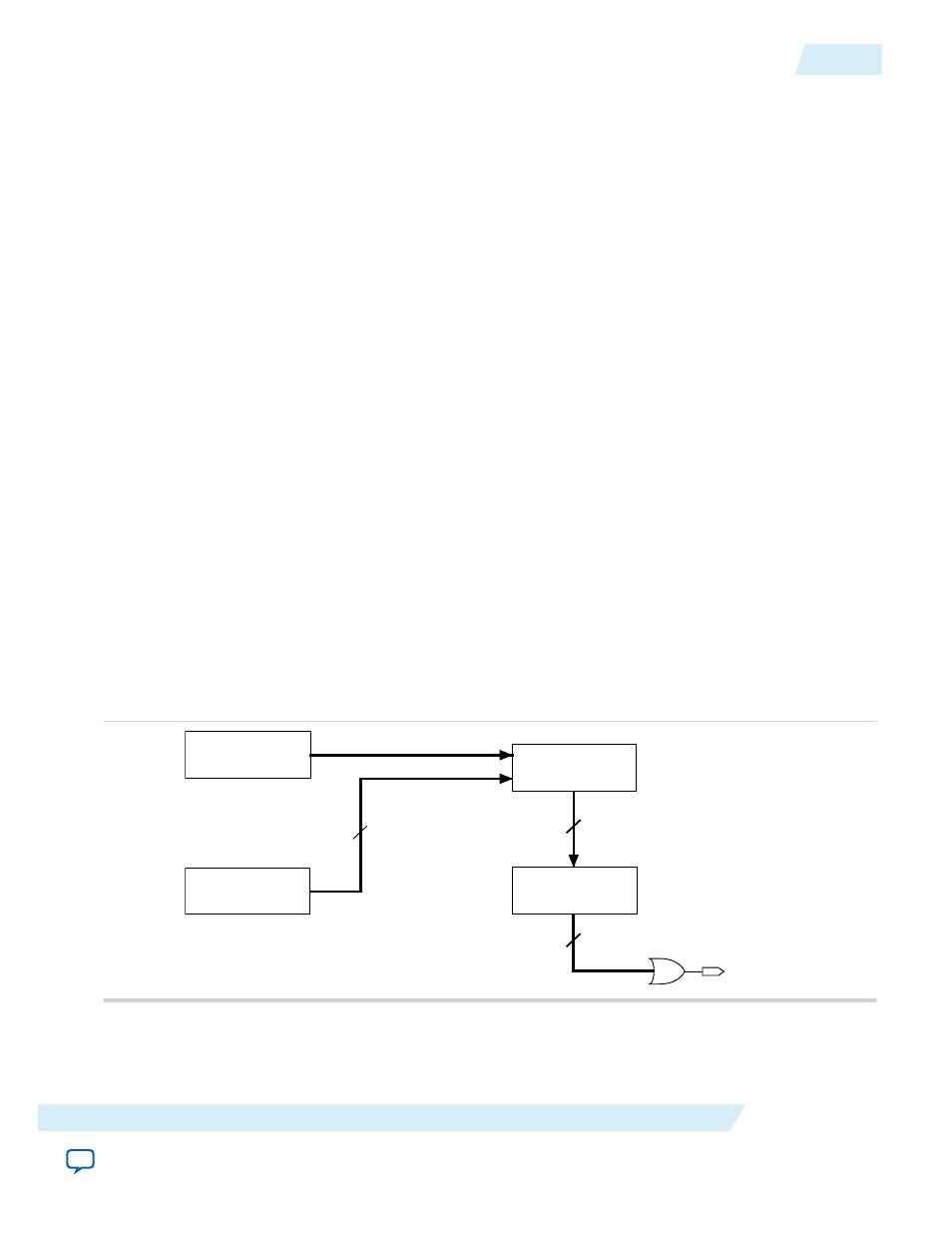
Error Detection Block
Figure 2-8: Error Detection Block Diagram
Error detection block diagram including the two related 32-bit registers—the signature register and the
storage register.
Control Signals
Error Detection
State Machine
32-bit Storage
Register
Compute & Compare
CRC
32-bit Signature
Register
32
32
32
CRC_ERROR
There are two sets of 32-bit registers in the error detection circuitry that store the computed CRC
signature and pre-calculated CRC value. A non-zero value on the signature register causes the
CRC_ERROR
pin to go high.
UG-M10CONFIG
2015.05.04
Configuration Error Detection
2-19
MAX 10 FPGA Configuration Schemes and Features
Altera Corporation