Remote system upgrade circuitry, Remote system upgrade circuitry signals, Figure 2-4: remote system upgrade circuitry – Altera MAX 10 FPGA User Manual
Page 14
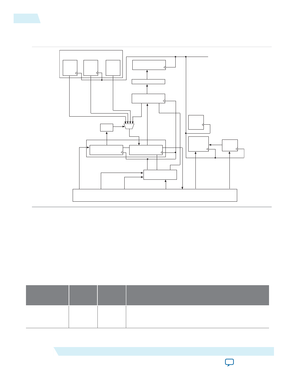
Remote System Upgrade Circuitry
Figure 2-4: Remote System Upgrade Circuitry
Status Register (SR)
Previous
State
Register 2
Bit[31..0]
State
Register 1
Bit[31..0]
Current
State
Logic
Bit[33..0]
Internal Oscillator
Control Register
Bit [38..0]
Logic
Input Register
Bit [38..0]
update
Logic
Bit [40..39]
dout
din
Bit [38..0]
dout
din
capture
Shift Register
clkout capture
update
Logic
clkin
RU_DIN
RU_SHIFTnLD
RU_CAPTnUPDT
RU_CLK
RU_nRSTIMER
Logic Array
RU
Reconfiguration
State
Machine
User
Watchdog
Timer
RU
Master
State
Machine
timeout
RU_nCONFIG
RU_DOUT
Previous
The remote system upgrade circuitry does the following functions:
• Tracks the current state of configuration
• Monitors all reconfiguration sources
• Provides access to set up the application configuration image
• Returns the device to fallback configuration if an error occurs
• Provides access to the information on the failed application configuration image
Remote System Upgrade Circuitry Signals
Table 2-6: Remote System Upgrade Circuitry Signals for MAX 10 Devices
Core Signal Name
Logical
Signal
Name
Input/
Output
Description
RU_DIN
regin
Input
Use this signal to write data to the shift register on the rising
edge of
RU_CLK
. To load data to the shift register, assert
RU_
SHIFTnLD
.
2-10
Remote System Upgrade Circuitry
UG-M10CONFIG
2015.05.04
Altera Corporation
MAX 10 FPGA Configuration Schemes and Features