Remote system upgrade flow – Altera MAX 10 FPGA User Manual
Page 13
Remote System Upgrade Flow
Both the application configuration images, image 0 and image 1, are stored in the CFM. The MAX 10
device loads either one of the application configuration image from the CFM.
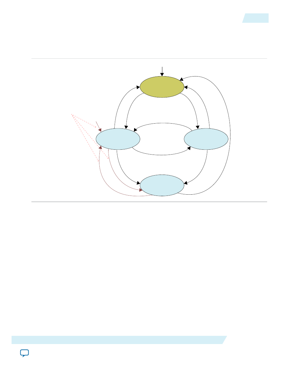
Figure 2-3: Remote System Upgrade Flow for MAX 10 Devices
Sample CONFIG_SEL pin
Image 0
Image 1
CONFIG_SEL=0
CONFIG_SEL=1
Wait for Reconfiguration
Power-up
Rec
onfigur
ation
Rec
onfigur
ation
Rec
onfigur
ation
First Error Occurs
First Error Occurs
Second Error Occurs
Flow when Auto-reconfigure
from secondary image when
initial image fails is disabled.
Second Error Occurs
Power-up
Error O
ccurs
Reconfiguration
The remote system upgrade feature detects errors in the following sequence:
1. After power-up, the device samples the
CONFIG_SEL
pin to determine which application configuration
image to load. The
CONFIG_SEL
pin setting can be overwritten by the input register of the remote
system upgrade circuitry for the subsequent reconfiguration.
2. If an error occurs, the remote system upgrade feature reverts by loading the other application configu‐
ration image. These errors cause the remote system upgrade feature to load another application
configuration image:
• Internal CRC error
• User watchdog timer time-out
3. Once the revert configuration completes and the device is in user mode, you can use the remote system
upgrade circuitry to query the cause of error and which application image failed.
4. If a second error occurs, the device waits for a reconfiguration source. If the Auto-restart configura‐
tion after error is enabled, the device will reconfigure without waiting for any reconfiguration source.
5. Reconfiguration is triggered by the following actions:
• Driving the
nSTATUS
low externally.
• Driving the
nCONFIG
low externally.
• Driving
RU_nCONFIG
low.
UG-M10CONFIG
2015.05.04
Remote System Upgrade Flow
2-9
MAX 10 FPGA Configuration Schemes and Features
Altera Corporation