Remote system upgrade input register – Altera MAX 10 FPGA User Manual
Page 16
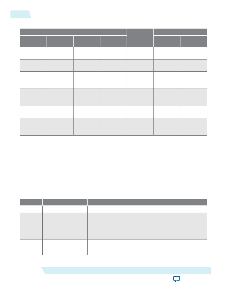
Table 2-7: Control Inputs to the Remote System Upgrade Circuitry
Remote System Upgrade Circuitry Control Inputs
Operation
Mode
Input Settings for Registers
RU_SHIFTnLD
RU_CAPTnUPDT
Shift register
[40]
Shift register
[39]
Shift
Register[38:0]
Input
Register[38:0]
0
0
Don't Care
Don't Care
Update
Shift Register
[38:0]
Shift Register
[38:0]
0
1
0
0
Capture
Current State
Input
Register[38:0]
0
1
0
1
Capture
{8’b0,
Previous State
Application1}
Input
Register[38:0]
0
1
1
0
Capture
{8’b0,
Previous State
Application2}
Input
Register[38:0]
0
1
1
1
Capture
Input
Register[38:0]
Input
Register[38:0]
1
Don't Care
Don't Care
Don't Care
Shift
{ru_din, Shift
Register
[38:1]}
Input
Register[38:0]
The following shows examples of driving the control inputs in the remote system upgrade circuitry:
• When you drive
RU_SHIFTnLD
high to 1’b1, the shift register shifts data on each rising edge of
RU_CLK
and
RU_CAPTnUPDT
has no function.
• When you drive both
RU_SHIFTnLD
and
RU_CAPTnUPDT
low to 1’b0, the input register is loaded with
the contents of the shift register on the rising edge of
RU_CLK
.
• When you drive
RU_SHIFTnLD
low to 1’b0 and RU_CAPTnUPDT high to 1’b1, the shift register
captures values on the rising edge of
RU_DCLK
.
Remote System Upgrade Input Register
Table 2-8: Remote System Upgrade Input Register for MAX 10 Devices
Bits
Name
Description
38:14
Reserved
Reserved—set to
0
.
13
ru_config_sel
• 0: Load configuration image 0
• 1: Load configuration image 1
This bit will only work if the
ru_config_sel_overwrite
bit is set
to
1
.
12
ru_config_sel_
overwrite
• 0: Disable overwrite
CONFIG_SEL
pin
• 1: Enable overwrite
CONFIG_SEL
pin
2-12
Remote System Upgrade Input Register
UG-M10CONFIG
2015.05.04
Altera Corporation
MAX 10 FPGA Configuration Schemes and Features