Dialogic DSI SPCI Network Interface Boards User Manual
Page 75
Dialogic
®
DSI SPCI Network Interface Boards Programmer's Manual Issue 5
75
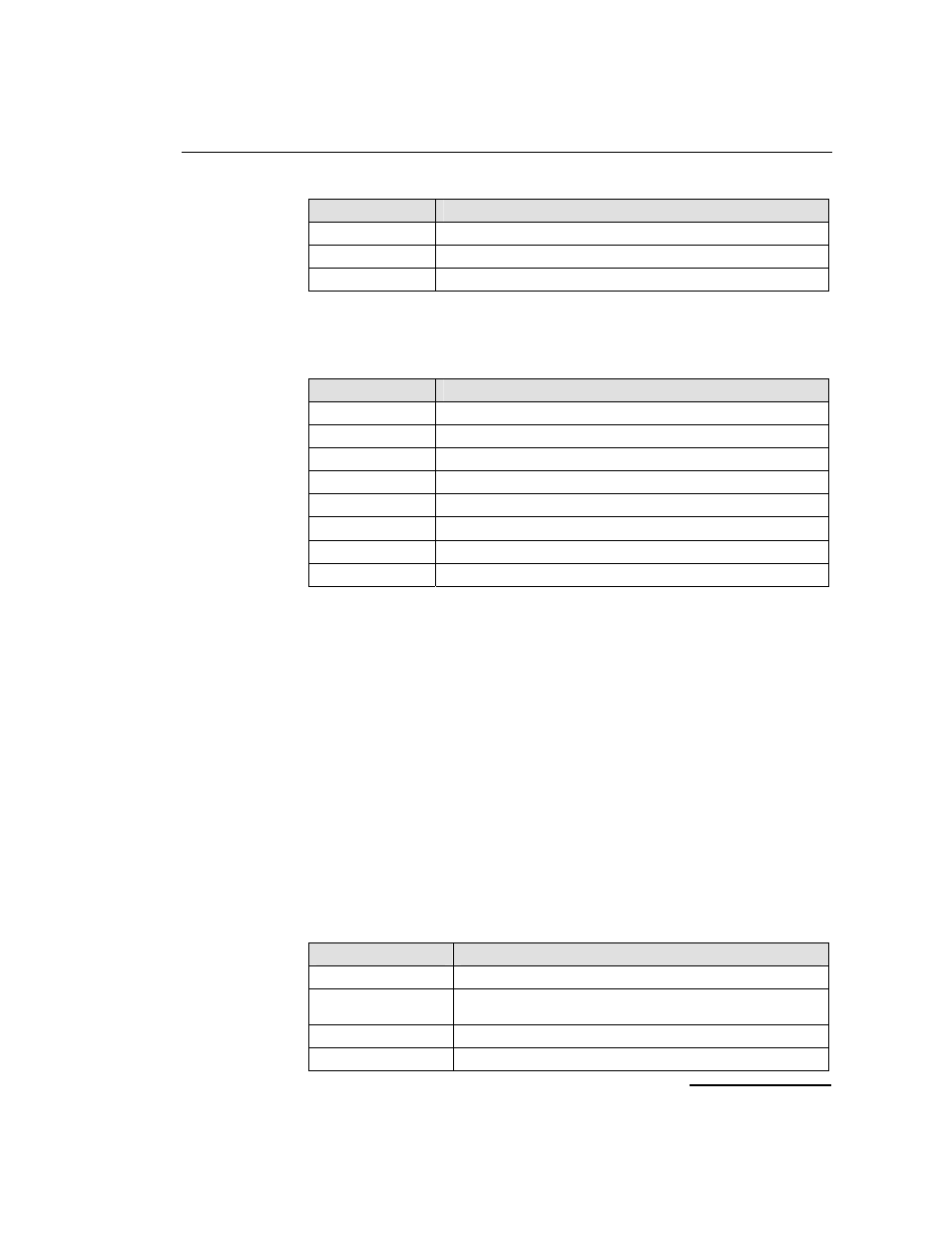
Value
Bus speed
0 No
change
2
4.096 MHz (Reserved for future use)
3 8.192
MHz
clk_mode
This parameter determines the clocking mode for the DSI SPCI Board, the
permissible values are as follows:
Value
Clock Mode
0 No
change
1
CT bus Primary Master, driving Clock Set A
2
CT bus Secondary Master, driving Clock Set B
3
CT bus Slave, initially using Clock Set A
4
CT bus disabled
10
CT bus Primary Master, driving Clock Set B
11
CT bus Secondary Master, driving Clock Set A
12
CT bus Slave, initially using Clock Set B
When mode 4 is selected ("CT bus disabled"), the DSI SPCI Board is
electrically isolated from the other boards using the CT bus. The CT bus
connection commands may still be used, but the connections made are only
visible to this board. The on-board clocks are synchronized to the configured
pll_clk_src reference.
If the DSI SPCI Board is configured to be Slave to the CT bus, then it
automatically switches between using Clock Set A and Clock Set B if it detects
a failure on the current clock set.
When a board is acting as Primary Master, it uses the clock reference set by
the pll_clk_src parameter to drive the CT bus clock.
As Secondary Master, the pll_clk_src must be set to an appropriate source
ready for use if the board acting as Primary Master stops driving the CT bus
clock. Until this time, the on-board clocks on the Secondary Master board are
synchronized to the CT bus clock provided by the Primary Master.
pll_clk_src
This parameter determines the source of the PLL reference clock, the
permissible values are:
Value
PLL Clock Source
0 No
change
1
Clock recovered from one of the line interfaces according to priority
order.
5 Local
reference
oscillator
7 NETREF
1