Dialogic DSI SPCI Network Interface Boards User Manual
Page 55
Dialogic
®
DSI SPCI Network Interface Boards Programmer's Manual Issue 5
55
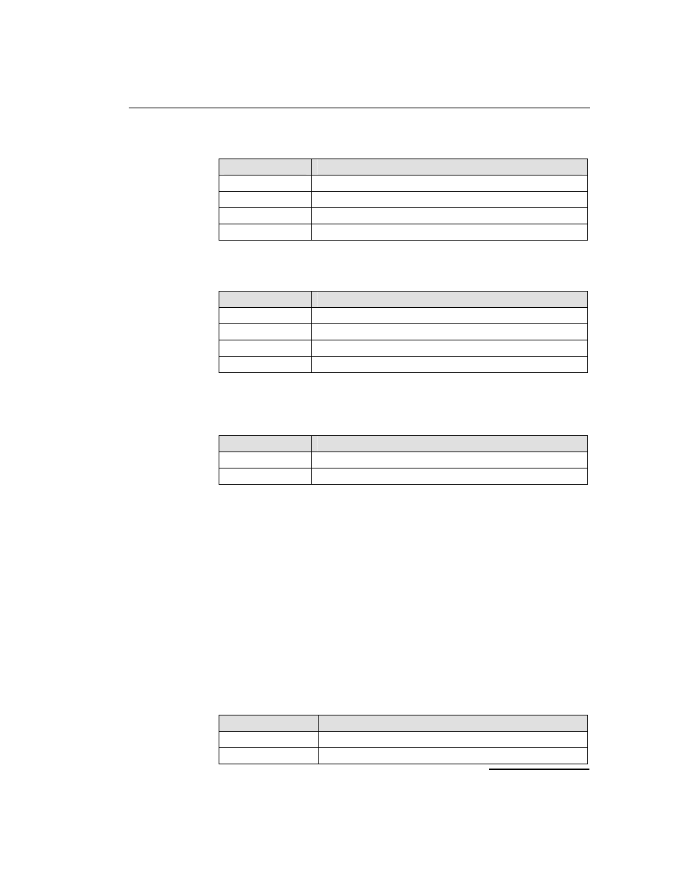
frame_format
Description
1
E1 double frame (E1 only).
2
E1 CRC4 multiframe (E1 only).
4
D3/D4 (Yellow alarm = bit 2 in each channel) (T1 only).
7
ESF (Yellow alarm in data link channel) (T1 only).
crc_mode
The CRC mode taken from the following table:
crc_mode
Description
1
CRC generation disabled.
2
CRC4 enabled (frame_format must be set to 2).
3
CRC4 compatibility mode (frame_format must be set to 2).
4
CRC6 enabled (frame_format must be set to 7).
build_out
Configurable line build out is not supported by the board, so the following
fixed values must be used.
Build_out
Description
0
Setting for E1 devices.
1 Setting
for
T1
devices.
faw
The 8 bit value to be used for any E1 frame alignment word bit positions that
are not modified by other options. This allows the spare bit designated "For
International Use" to be set by the user when CRC4 mode is disabled. Valid
values are 0x9b or 0x1b. When using T1, this parameter must be set to zero.
[E1 default = 0x9b].
nfaw
The 8 bit value to be used for any E1 non-frame alignment word bit positions
that are not modified by other options. Normally, this parameter is set to
0x9f for E1 operation and set to zero for T1.
ais_gen
The (initial) mode used to generate the Alarm Indication Signal (Blue Alarm)
taken from the following table. The user may subsequently modify the setting
of the outgoing signal using the LIU_MSG_CONTROL message.
ais_gen
Description
1
Disabled - do not generate AIS / Blue alarm.
2
Enabled - generate AIS / Blue alarm.