Tilt compensation module – TeeJet CenterLine User Guide v2.02 User Manual
Page 45
CenterLine 2.02
98-05054 R6
41
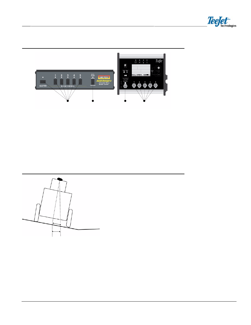
Figure 3-18: Switch Setting Example for Swath Manager 5
TILT COMPENSATION MODULE
CenterLine must be loaded with Software Version 1.10 or higher to be compatible with the Tilt Com-
pensation Module. The Tilt Module must be leveled (refer to CHAPTER 2 - LEVEL for additional
information) and the antenna height must be set (refer to CHAPTER 2 - ANTENNA for additional
information). When operating the Tilt Compensation Module, the position data coming from the GPS
receiver will be compensated for vehicle tilt errors. Corrected information will be sent to the console.
When the vehicle experiences a sideways tilt, all guidance information is affected. For example, if
the GPS sensor is 12 feet / 3.65 meters above the ground, a 10 degree tilt gives a 2 foot / 0.61 meter
positioning error.
Figure 3-19: Tilt Sensor Example
There are three LEDs visible on the Tilt Sensor that indicate the following:
•
Blue - blinks two times per second when the unit is powered and running
•
Green - steady ON when tilt correction is enabled; otherwise OFF
•
Yellow - Blinks one time per second when valid GPS location data is being received
(NMEA-0183 GGA)
Master and Boom
Sections ON
Auto Boom
Engaged
Master ON
Boom
Sections OFF
Swath Manager 5
Rate Controller
Position Error
2’
2’
10
o
1
2
’
Level Ground
10 degree s
lope
GPS antenna