Appendices ~ appendix b: pinouts – ClearOne comm PSR1212 User Manual
Page 90
Appendices
~ Appendix B: Pinouts
84
Technical Services Group ~ 1-800-283-5936 (USA) ~ 1-801-974-3760
Appendix B: Pinouts
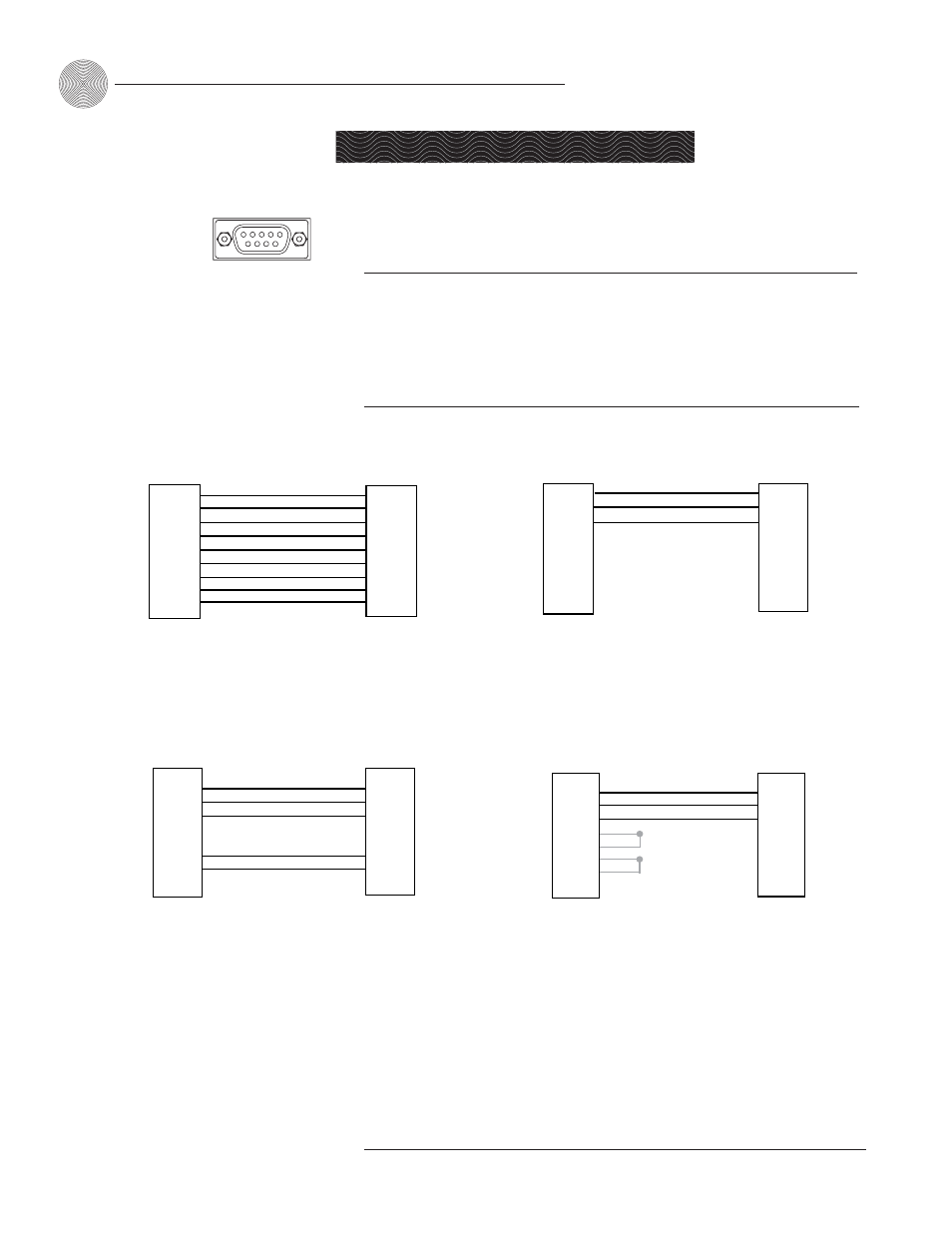
RS-232 COM DCE port pinout (female)
Pin Number
Control
Pin Number
Control
1 DCD
6
DSR
2 TXD
7
CTS
3 RXD
8
RTS
4 DTR
9
No
connection
5 Ground
1
5
6
9
Figure B.1. RS-232 connector
PC
PSR1212
DB-9
Male
DB-9
Female
TXD (Pin 2)
RXD (Pin 3)
DTR (Pin 4)
GND (Pin 5)
CTS (Pin 7)
RTS (Pin 8)
TXD (Pin 2)
RXD (Pin 3)
GND (Pin 5)
CTS (Pin 7)
RTS (Pin 8)
Pin 6
Pin 9
Pin 4
Pin 1
Pin 9
Pin 6
Pin 1
PSR1212
Modem
Pin 3
Pin 2
Pin 3
Pin 7
DB-9
Male
DB-25
Female
Pin 5
Pin 2
AMX
PSR1212
TXD (Pin 2)
RXD (Pin 3)
GND (Pin 5)
RX2 (White)
TX2 (Red)
GND (Black)
DB-9
Female
Phoenix
Connectors
CTS (Pin 7)
RTS (Pin 8)
RTS2 (Green)
CTS2 (Blue)
AMX
Modem
DB-25
Female
DB-9
Male
TXD (Pin 2)
RXD (Pin 3)
GND (Pin 5)
CTS (Pin 7)
RTS (Pin 8)
DTR (Pin 4)
TXD (Pin 2)
RXD (Pin 3)
RTS (Pin 7)
GND (Pin 6)
RTS (Pin 20)
CTS (Pin 4)
GND (Pin 5)
Figure B.2. PSR1212 to PC RS-232 connections
Figure B.3. PSR1212 to Modem RS-232 Connections
Figure B.5. Modem to AMX RS-232 Connections
Figure B.4. PSR1212 to AMX RS-232 Connections
ClearOne recommends
that all nine pins be
connected to avoid
!