Installation ~ hardware setup – ClearOne comm PSR1212 User Manual
Page 16
Installation
~ Hardware Setup
10
Technical Services Group ~ 1-800-283-5936 (USA) ~ 1-801-974-3760
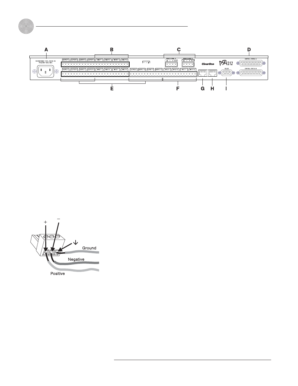
To connect the unit
1.
Place the unit in a standard 19-inch rack and attach it securely.
2.
If you are using a custom controller for control and status, plug it into the
DB-25 Control/Status A or B port [D].
If you are using an external RS-232 controller, connect it to the
RS-232 port [I].
3.
Wire the inputs and outputs to the PSR1212 using the provided three-
terminal Phoenix push-on connectors. These connectors are designed for
easy wiring; simply insert the desired wire into the appropriate connector
opening and tighten down the top screw.
•
Inputs 1–8 [B] Mic or line level inputs
•
Inputs 9–12 [F] Line level inputs only
•
Outputs 1–12 [E] Line level outputs
4.
If you are using a ClearOne Control Panel or XAP IR Remote, wire it to the
RS-485 port [C] using one of the provided four-terminal Phoenix push-on
connectors.
5.
Plug in the PSR1212 to complete the installation. The power output [A]
will operate at any level between 100–240VAC and 50–60Hz.
If you are installing only one PSR1212 and are not connecting it to any other XAP
or PSR1212 units, you have completed the hardware installation.
Expansion Bus
In
Out
Figure 2.2. PSR1212 rear-panel connectors
The three terminals in
the Phoenix connector
correspond with the
rear-panel audio contacts (from
left to right): + (positive), –
(negative), and
(ground).
-
Figure 2.3. Phoenix push-on connector