Installation ~ lcd programming, Matr ix, Meter ref erence p oint – ClearOne comm PSR1212 User Manual
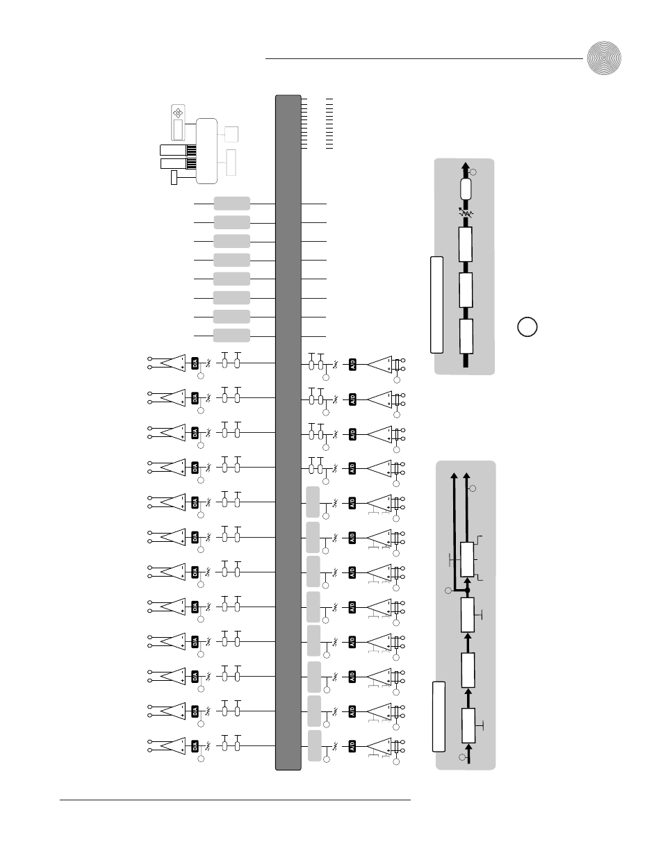
Page 25: Figure 2.7. meter r e ference p o int diagram, Assignab le processing, Control logic, Input processing
19
Installation
~ LCD Programming
Technical Services Group ~ 1-800-283-5936 (USA) ~ 1-801-974-3760
Fine Input Gain
Phantom
Po
w
e
r
On/Off
Mic 55, 25
Line
Fine Input Gain
Fine Input Gain
Fine Input Gain
Fine Input Gain
Fine Input Gain
Fine Input Gain
Fine Input Gain
On
On
On
On
On
Off
Off
Off
Off
Off
Mute
Fine Input Gain
Input
Processing
On
Off
Mute
Output Gain
Off
NOM
On
Off
Mute
Fine Input Gain
On
Off
Mute
Fine Input Gain
On
Off
Mute
Fine Input Gain
Expansion Bus In/Out
Input 1
Input 2
Input 3
Input 4
Input 5
Input 6
Input 7
Input 8
Input 9
Input 10
Input 11
Input 12
Output 1
Output 2
Output 3
Output 4
Output 5
Output 6
Output 7
Output 8
Output 9
Output 10
Output 11
Output 12
Z Mixing Bus
On
Off
Mute
Output Gain
Off
NOM
On
Off
Mute
Output Gain
Off
NOM
On
Off
Mute
Output Gain
Off
NOM
On
Off
Mute
Output Gain
Off
NOM
On
Off
Mute
Output Gain
Off
NOM
On
Off
Mute
Output Gain
Off
NOM
On
Off
Mute
Output Gain
Off
NOM
On
Off
Mute
Output Gain
Off
NOM
On
Off
Mute
Output Gain
Off
NOM
On
Off
Mute
Output Gain
Off
NOM
On
Off
Mute
Output Gain
Off
NOM
Phantom
Po
w
e
r
On/Off
Phantom
Po
w
e
r
On/Off
Phantom
Po
w
e
r
On/Off
Phantom
Po
w
e
r
On/Off
Phantom
Po
w
e
r
On/Off
Phantom
Po
w
e
r
On/Off
Phantom
Po
w
e
r
On/Off
Mic 55, 25
Line
Mic 55, 25
Line
Mic 55, 25
Line
Mic 55, 25
Line
Mic 55,25
Line
Mic 55, 25
Line
Mic 55, 25
Line
Matr
ix
Input
Processing
Input
Processing
Input
Processing
Input
Processing
Input
Processing
Input
Processing
Input
Processing
Assignable
Processing
Assignable
Processing
Assignable
Processing
Assignable
Processing
Assignable
Processing
Assignable
Processing
Assignable
Processing
Assignable
Processing
A
A
B
B
C
C
D
D
E
E
F
F
G
G
H
H
Processing outputs are looped bac
k into the matr
ix.
M
M
M
M
M
M
M
M
M
M
M
M
M
T
o
Matr
ix
F
rom Matr
ix
Dela
y
Compressor
15 Filters
Assignab
le Processing
All P
ass
Lo
w
P
ass
High P
ass
Lo
w S
helving
H
igh S
helving
500mS
Gain Adjust
Mute
M
PE
Q
CD
H
or
n
Bessel Crosso
v
e
r
Butterw
or
th
Linkw
itz-Rile
y
Control Bus
Y Mixing Bus
X Mixing Bus
W Mixing Bus
V Mixing Bus
U Mixing Bus
T Mixing Bus
S Mixing Bus
R Mixing Bus
Q Mixing Bus
P Mixing Bus
O Mixing Bus
Control/Status
B
Control/Status
A
Control
Logic
F
ront P
anel
Control
Expansion Bus
RS-485
Control
Netw
or
k
RS-485
AG
C
On
Off
Mute
A
utomix
er
4 Filters
Non-Gated A
udio
Gated A
udio
T
o
Matr
ix
Input Processing
On
Off
System-Wide
A
u
tomixing
P
a
ra
meters
M
icrophone Activ
ation
A
uto gate/M
an
ual gate/O
n/O
ff
C
hair
m
an O
v
err
ide
O
n/O
ff
A
daptiv
e Am
bient
M
All P
ass
Lo
w P
ass
High P
ass
PEQ
M
On
On
On
On
On
On
On
On
On
On
On
On
M
= Meter Ref
erence P
oint
Notch
Notch
M
Pre-gain
Meter
P
ost-gain
Meter
M
Pre-gain
Meter
M
Pre-gain
Meter
M
Pre-gain
Meter
M
Pre-gain
Meter
M
Pre-gain
Meter
M
Pre-gain
Meter
M
Pre-gain
Meter
M
Pre-gain
Meter
M
Pre-gain
Meter
M
Pre-gain
Meter
M
Pre-gain
Meter
M
P
ost-gain
Meter
M
P
ost-gain
Meter
M
P
ost-gain
Meter
M
P
ost-gain
Meter
M
P
ost-gain
Meter
M
P
ost-gain
Meter
M
P
ost-gain
Meter
M
P
ost-gain
Meter
M
P
ost-gain
Meter
M
P
ost-gain
Meter
M
P
ost-gain
Meter
P
ost-processing
Meter
P
ost-gain
Meter
M
P
ost-gating
Meter
P
ost-processing
Meter
P
ost-gain
Meter
P
ost-gain
Meter
P
ost-gain
Meter
P
ost-gain
Meter
P
ost-gain
Meter
P
ost-gain
Meter
P
ost-gain
Meter
P
ost-gain
Meter
P
ost-gain
Meter
P
ost-gain
Meter
P
ost-gain
Meter
P
ost-gain
Meter
RS-232
AG
C
AG
C
AG
C
AG
C
Figure 2.7. Meter R
e
ference P
o
int diagram