Compaq AA-RHGWC-TE User Manual
Page 242
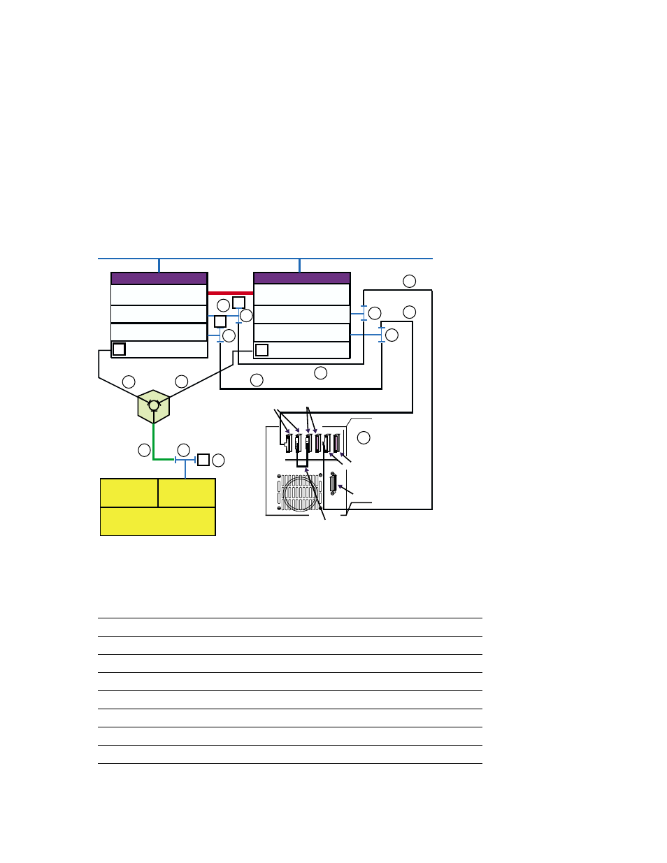
Figure 8–10: TruCluster Server Cluster with a TL892 on Two Shared SCSI
Buses
KZPBA-CB (ID 7)
Memory
Channel
Interface
Memory Channel
KZPBA-CB (ID 6)
Member System 1
DS-DWZZH-03
T
T
T
2
1
4
1
3
StorageWorks
RAID Array 7000
HSZ70
HSZ70
Controller B
Controller A
T
KZPBA-CB (ID 7)
5
5
6
7
6
7
KZPBA-CB (ID 6)
T
T
Network
T
Member System 2
Memory Channel
KZPBA-CB (ID 6)
KZPBA-CB (ID 7)
T
5
5
7
7
ZK-1762U-AI
Library
Robotics
Expansion
Unit
Interface
DLT1
TL892
DLT2
1 Ft
SCSI Bus
Jumper
Table 8–7 shows the components used to create the cluster shown in
Figure 8–10.
Table 8–7: Hardware Components Used to Create the Configuration Shown
in Figure 8–9
Callout Number
Description
1
BN38C or BN38D cable
a
2
BN37A cable
b
3
H8861-AA VHDCI trilink connector
4
H8863-AA VHDCI terminator
5
BN21W-0B Y cable
6
H879-AA terminator
7
328215-00X, BN21K, or BN21L cable
c
a The maximum length of the BN38C (or BN38D) cable on one SCSI bus segment must not exceed 25 meters.
b The maximum length of the BN37A cable must not exceed 25 meters.
c The maximum combined length of these cables must not exceed 25 meters.
8–28 Configuring a Shared SCSI Bus for Tape Drive Use