Cannon Instrument CMRV-4500 User Manual
Page 66
60
CANNON
®
Mini-Rotary Viscometer CMRV-4500 Instruction & Operation Manual
Version 1.1e—October, 2011 •
CANNON
®
Instrument Company
2139 High Tech Road • State College, PA • 16803 • USA
Winding rotors
7. To wind the rotors in preparation for the profile, slide the pulley-
wheel assembly along the track until the pulley is aligned with the
first viscometric cell. Use the engraved lines on the slide bar as a
guide to determine the proper position of the left side of the pulley-
wheel block.
8. Place the loop of a thread over the left end of the crossbar at the top
of the rotor shaft.
9. Pass the free end of the thread (the end with the plastic ring) over the
pulley-wheel and allow it to hang freely in front of the viscometer.
While holding the rotor motionless, hook a light weight, such as a
large paper clip, on the plastic ring to apply slight tension to the
thread.
10. Guiding the thread with your finger, turn the rotor clockwise to wind
the thread above the crossbar until the knot in the loop has been
wound around the rotor shaft. Then pass the thread below the cross-
bar and continue turning the rotor clockwise (as viewed from above)
to wind 20 closely spaced turns of thread around the shaft below the
crossbar without overlapping the turns. About 200 mm (8 inches) of
thread will remain. Place this remaining length of thread over the
upper bearing support plate so it hangs to the rear of the viscometer
and secure the rotor in place by lowering the rotor locking pin over
the rotor crossbar. You may need to turn the rotor slightly to align the
crossbar with the locking pin.
11. Repeat steps 8-10 for each of the remaining rotors/cells.
Plexiglas
®
cover placement
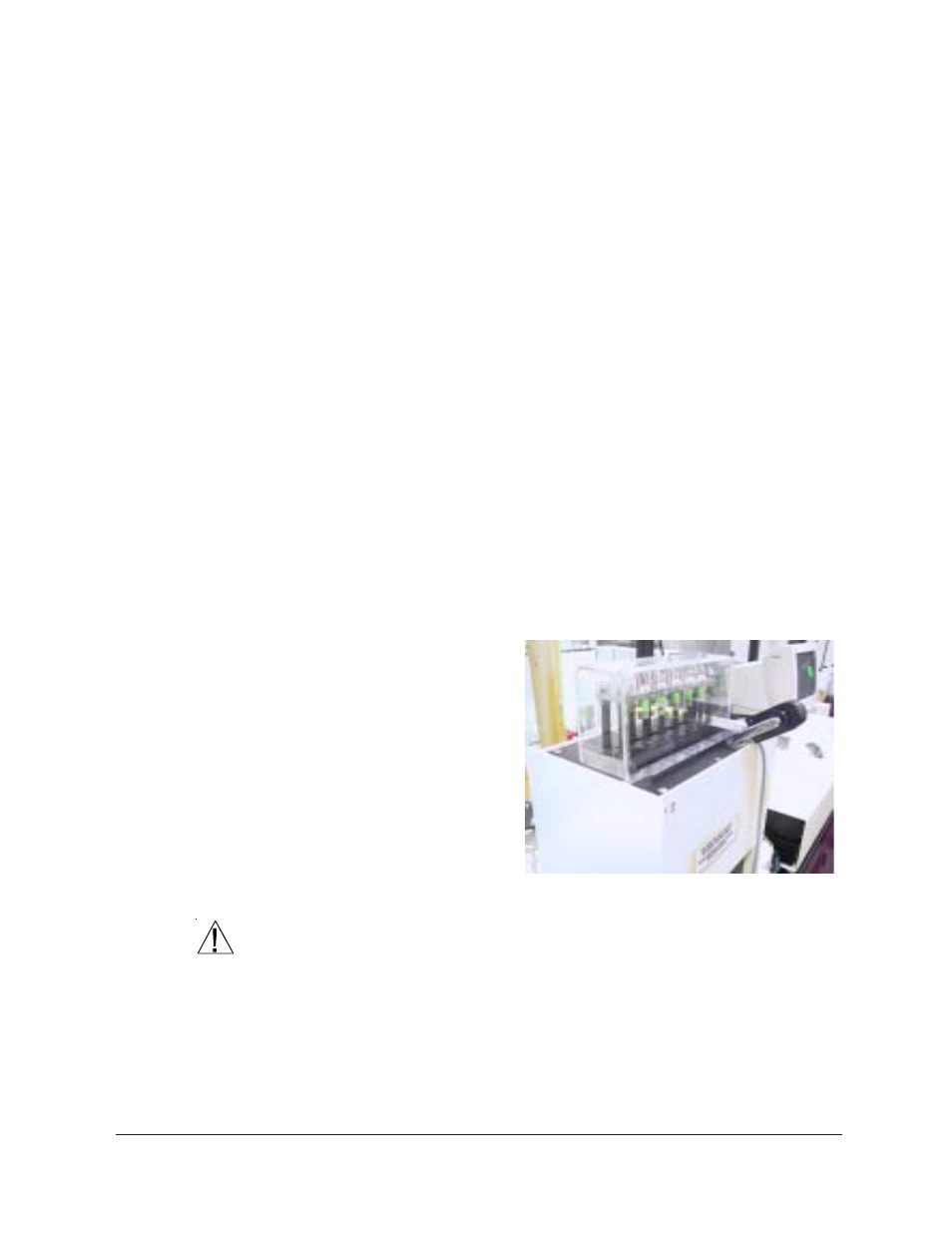
12. Place the Plexiglas
®
cover in position over
the top of the visco-
metric cells (see
photo). The small
hole which allows the
-46 to 30°C thermom-
eter to extend through
the cover should be
on the left when
viewed from the front
of the viscometer.
CAUTION
If a thermometer is not in place during CMRV-4500 testing, you should
seal the thermometer opening in the Plexiglas
®
cover, particularly when
the humidity of the ambient air is high. Otherwise, moisture may con-
dense and freeze on the top of the block.
13. CMRV users following the ASTM D 4684 or ASTM D 3829 method-
ology should insert a flexible 3/16"-OD tube from their dry gas
supply and regulator through the dry gas purge in the Plexiglas
®
CMRV 4500 with rotors wound and
Plexiglas
®
cover in place.