Tubing connections, Filling the air/water heat exchanger – Cannon Instrument CMRV-4500 User Manual
Page 18
12
CANNON
®
Mini-Rotary Viscometer CMRV-4500 Instruction & Operation Manual
Version 1.1e—October, 2011 •
CANNON
®
Instrument Company
2139 High Tech Road • State College, PA • 16803 • USA
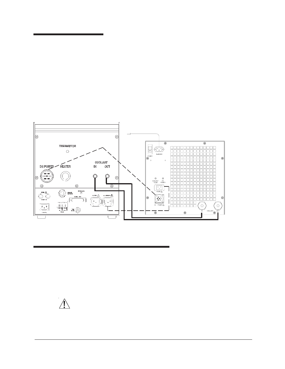
Tubing connections
There are two tubing connections on the rear of the CMRV-4500 housing
(see diagram, next page). The fitting on the left is the coolant
INLET
(for
introducing coolant to the CMRV-4500) and the fitting on the right of the
rear panel is the coolant
OUTLET
(for returning coolant to the Ex
changer). Clamp the open ends of both hoses to these fittings, then secure
the hoses to the appropriate
bulkhead fittings on the Air/Water Heat
Exchanger using the bulkhead inserts provided with the tubing (see
Figure). The fittings will snap into place. To release and remove the
tubing from the Air/Water Heat Exchanger, push down on the button on
the bulkhead fittings to release the connector locking clips.
CMRV-4500 tubing (solid lines) and electrical (dotted lines) controller/AWHE connections
Filling the Air/Water Heat Exchanger
Obtain a supply of quality automotive antifreeze (ethylene glycol) and
mix it with water in a ratio of 30 percent antifreeze to 70 percent water.
Do not mix antifreeze types in the Air-Water Heat Exchanger.
After you have secured the Exchanger tubing connections (see previous
section) pour this antifreeze/water mixture into the reservoir opening on the
top of the Air/Water Heat Exchanger until it is full (approximately 4 liters).
CAUTION
Ethylene glycol is a toxic substance. Use proper safety precautions when
handling. Follow appropriate MSDS instructions.
NOTE
Depending on the amount of fluid displacement in the coolant lines, it
may be necessary to add additional antifreeze/water mixture to the