Cmrv-4500 apparatus description, Cmrv-4500 unit/accessories – Cannon Instrument CMRV-4500 User Manual
Page 13
7
CANNON
®
Mini-Rotary Viscometer CMRV-4500 Instruction & Operation Manual
Version 1.1e—October, 2011 •
CANNON
®
Instrument Company
2139 High Tech Road • State College, PA • 16803 • USA
CHAPTER
3
CMRV-4500 APPARATUS
DESCRIPTION
CMRV-4500 unit/accessories
The CMRV-4500 unit con-
tains an aluminum block with
a heater for warming the
block. Nine viscometric cells
are closely fitted into nine
holes in the block (see photo).
There are also two thermom-
eter wells in the block.
Lower rotor bearing
Each viscometric cell
consists of an aluminum
block aperture with a
rotor resting in a stainless
steel cup at the base. The
rotor is attached to a rotor
shaft with a pivot point at
the bottom. The pivot
point fits a mating
conical depression at the
bottom of the stainless
steel cup; this mechanism
serves as the lower
bearing. The standard rotor composi-
tion is hardened stainless steel. The
drive line rotor composition is Delrin
®
(NOTE: The drive line rotors/pins/
weights must be purchased separately
from CANNON
®
.)
Upper rotor bearing
The upper bearing consists of a brass
insert at the top of the rotor shaft with
a 1.2 mm hole on the shaft axis. A
cylindrical rotor pin is inserted
through the upper bearing plate about
one or two millimeters into the hole
on the shaft axis.
CMRV-4 unit with rotors inserted
and thread wound on pulley-wheel
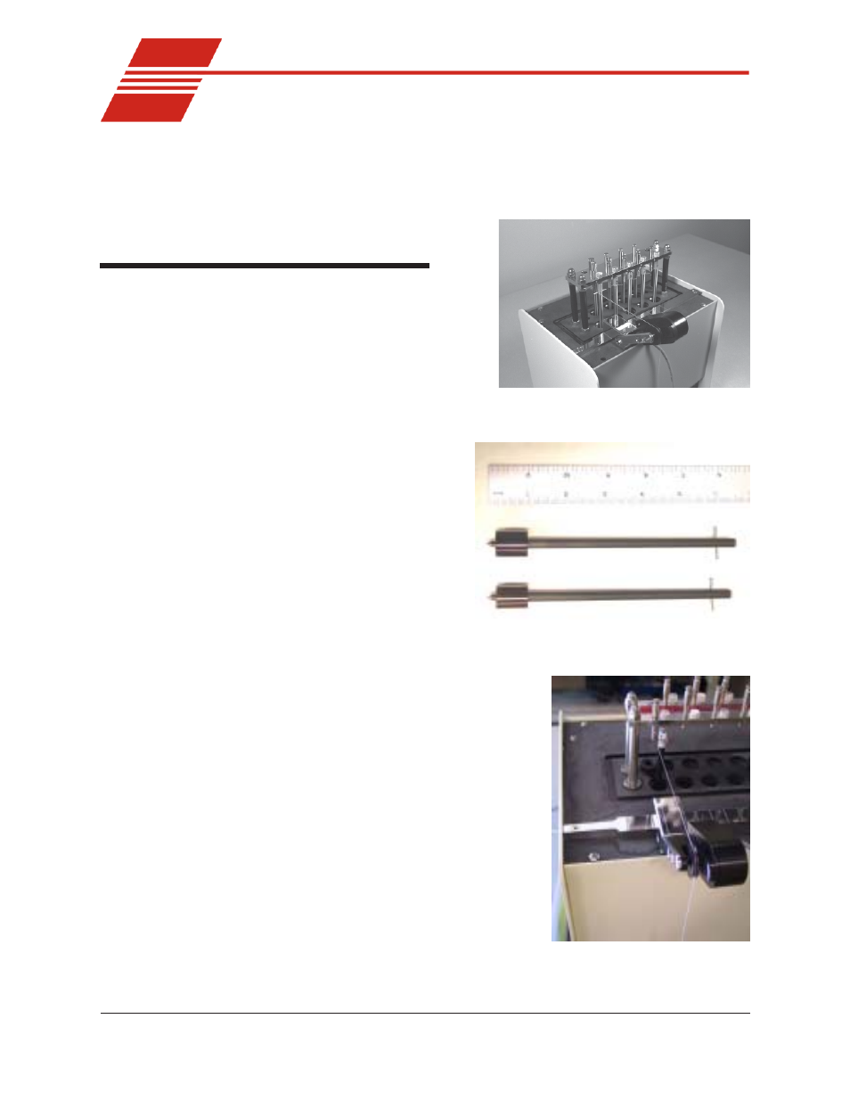
Rotor for oil testing (top) and
drive line lubricant testing
Upper bearing assembly with
rotor and rotor locking pin in
place