Cannon Instrument CMRV-4500 User Manual
Page 43
37
CANNON
®
Mini-Rotary Viscometer CMRV-4500 Instruction & Operation Manual
Version 1.1e—October, 2011 •
CANNON
®
Instrument Company
2139 High Tech Road • State College, PA • 16803 • USA
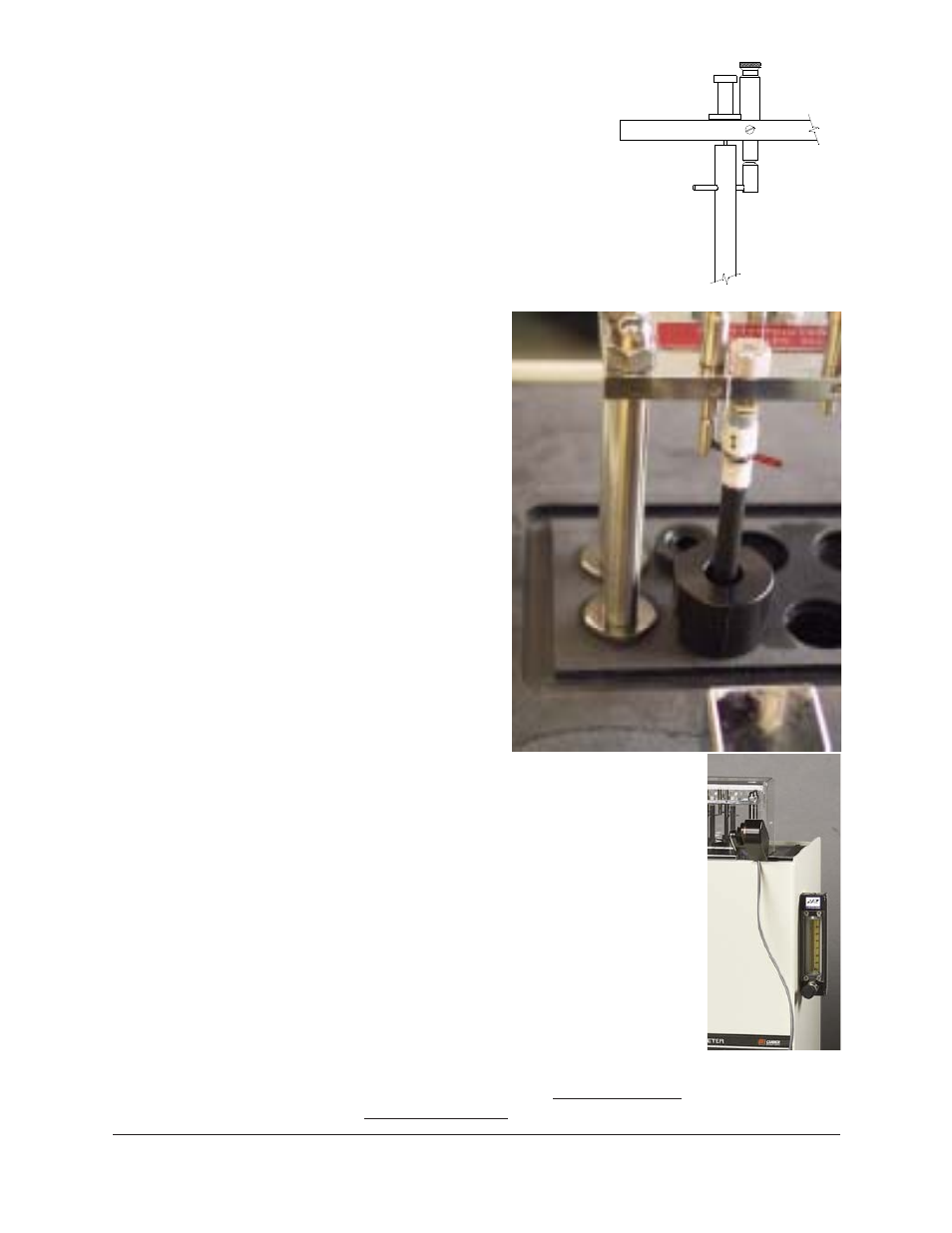
wound around the rotor shaft.
Then pass the thread below the
crossbar and continue turning the
rotor clockwise (as viewed from
above) to wind 20 closely spaced turns of
thread around the shaft below the crossbar
without overlapping the turns. About 200 mm
(8 inches) of thread will remain. Place this
remaining length of thread over the upper
bearing support plate so it hangs to the rear of
the viscometer
and secure the
rotor in place by
lowering the rotor
locking pin over
the rotor crossbar
(see figure and
photo). You may
need to turn the
rotor slightly to
align the crossbar
with the locking
pin.
8. Repeat steps 4-7
for each of the
remaining rotors/
cells.
Plexiglas
®
cover placement
9. Place the
Plexiglas
®
cover
in position over
the top of the
viscometric cells.
The small hole
which allows the -
46 to 30°C thermometer to extend through the
cover should be on the left when viewed from
the front of the viscometer.
10. CMRV users following the ASTM D 4684 or
ASTM D 3829 methodology should connect a
flexible 3/16"-OD tube from their dry gas
supply and regulator to the dry gas purge in the
Plexiglas
®
cover. The tubing may be removed,
along with the cover, prior to viscosity/yield
stress testing.
11. Whatever the methodology, the purge should
continue throughout the temperature profile
using dry gas at a flow rate between 20 and 30
milliliters per minute.
Wound rotor with cell
caps in place
CMRV with side-
mounted dry gas
purge