Electrical /serial connections – Cannon Instrument CMRV-4500 User Manual
Page 19
13
CANNON
®
Mini-Rotary Viscometer CMRV-4500 Instruction & Operation Manual
Version 1.1e—October, 2011 •
CANNON
®
Instrument Company
2139 High Tech Road • State College, PA • 16803 • USA
Exchanger when the unit commences operation. You will be able to
observe the liquid circulating inside the reservoir from the opening at the
top of the Exchanger during normal operation. If air bubbles are consis-
tently visible in the coolant lines, add additional mixture until the Ex-
changer is full.
CAUTION
The water-antifreeze mix should be replaced annually for reliable perfor-
mance and to prevent corrosion of internal components (see Flushing
and draining the Air/Water Heat Exchanger, this chapter).
Electrical /serial connections
A/W Heat Exchanger
Plug the male end of the
DC
power cable into the
DC POWER OUT
fitting on the rear panel of the Air/Water Heat Exchanger and turn the
locking clip clockwise to secure the connection. Attach the other end of
the cable to the receptacle labelled
DC POWER
at the back of the
CMRV-4500 unit (see figure, previous page). This connection provides
power to the thermoelectric cooling modules.
Insert the power cable for the Air/Water Heat Exchanger into the recep-
tacle on the Exchanger rear panel. Secure the power cable in place by
tightening the Phillips screw on the cable clamp.
Make sure the Air/Water Heat Exchanger power switch is in the
OFF
position; then insert the power line cord from the Exchanger into an
appropriate power source for your unit.
Before providing mains power to the unit, check the label on the rear
panel of the Exchanger to verify that the electrical specifications for the
unit match those of the power supply.
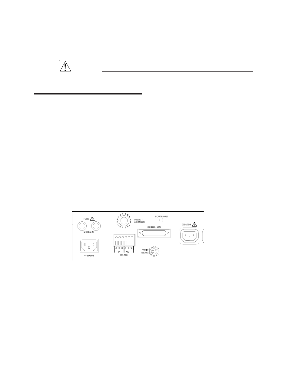
Figure 11: CMRV rear panel
Attach the M-F three-prong connector cable from the Exchanger
PUMP
outlet to the
PUMP
receptacle on the CMRV-4500 controller (see figures on
pages 12-13). This power connection permits CMRV-4500 control of pump
operation.
Thermistor
Insert the Lemo
®
plug from the temperature probe into the jack marked
TEMP PROBE
on rear of the CMRV controller (see Figure 11). Insert
the probe tip as far as it will go into the hole marked
THERMISTOR
on
the rear of the CMRV-4500 chassis.