Pulley-wheel installation – Cannon Instrument CMRV-4500 User Manual
Page 20
14
CANNON
®
Mini-Rotary Viscometer CMRV-4500 Instruction & Operation Manual
Version 1.1e—October, 2011 •
CANNON
®
Instrument Company
2139 High Tech Road • State College, PA • 16803 • USA
Heater
Insert the heater plug from the upper section of the CMRV-4500 housing
into the
HEATER
receptacle on the rear panel of the CMRV controller.
CMRV-4500 power cord
Make sure the CMRV-4500 power switch is in the
OFF
position. Then
insert the power line cord from the rear panel of the CMRV controller
into an appropriate power source for your unit
Before providing mains power to the unit, check the label on the rear
panel of the Exchanger to verify that the electrical specifications for the
unit match those of the power supply. Use only the supplied, approved
appliance cords for the CMRV.
Serial connections
To connect a single CMRV-4500 instrument to the host computer,
connect the computer cable to the RS-232, DB-25-pin socket at the rear
of the CMRV-4500 controller and secure the cable connection with the
two small screws on the ears of the plug. Attach the other end of the cable
to the RS-232 port at the rear of your computer.
NOTES
COM 2 and COM 4 use the same IRQ settings on most computers,
meaning that they cannot be used simultaneously. The COM 1 and
COM 3 ports have the same problem. Do not try to use a device on COM
4 if you are using COM 2 for the CMRV instrument.
Some display adaptors (in particular, S3, 8514A and ATI mach 8) have
an address conflict with COM 4 ports. If this is the case, you may need to
use another COM port or replace your current display adaptor.
RS-485 serial connections
To install multiple CMRV units using RS-485 serial cable connections,
see the multi-unit configuration instructions in APPENDIX D.
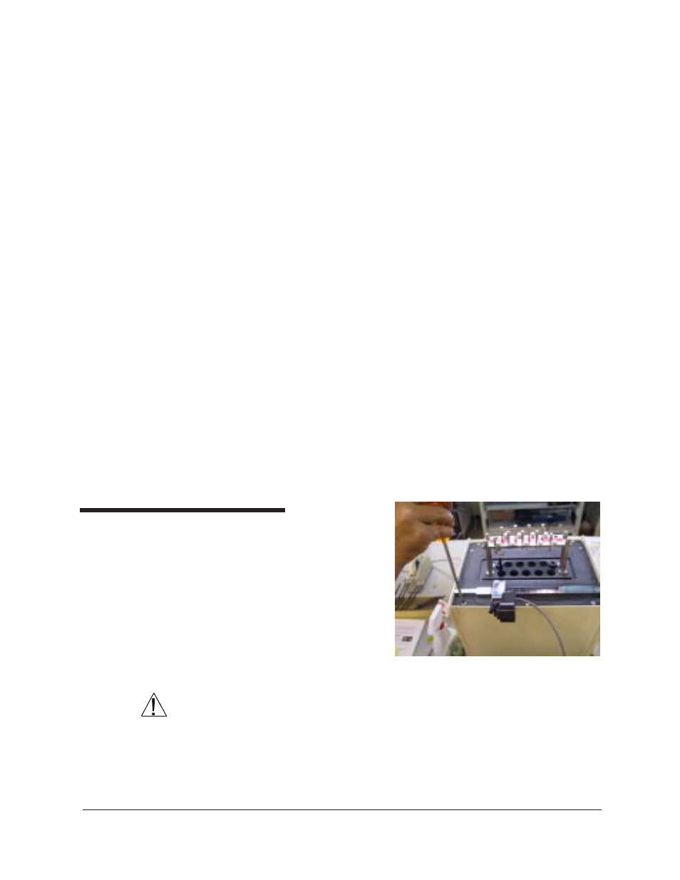
Pulley-wheel installation
To install the pulley-wheel
assembly atop the CMRV:
1. Remove the left screw
from the front of the
upper panel (see photo).
This will provide
clearance to install the
assembly on the slide
track.
CAUTION
Use care in handling the pulley-wheel assembly to avoid damage to the
wheel or the movement sensor.
2. Install the pulley-wheel assembly by sliding it onto the left end of the
slide track with the pulley-wheel facing out (see photo).
Removing screw to install pulley wheel