Cannon Instrument CMRV-4500 User Manual
Page 14
8
CANNON
®
Mini-Rotary Viscometer CMRV-4500 Instruction & Operation Manual
Version 1.1e—October, 2011 •
CANNON
®
Instrument Company
2139 High Tech Road • State College, PA • 16803 • USA
Rotor crossbar
The rotor crossbar is
used to hold the loop
at the end of the
thread. It also serves
as an indicator for
(optional) manual
timing of rotor
rotation.
Rotor locking pins
The rotor locking pins
are used to prevent
unwanted rotor rotation. When the locking pin is lowered over the rotor
crossbar (see photo), rotation is prevented. When the pins are in the
raised (detent) position, the rotors are free to rotate.
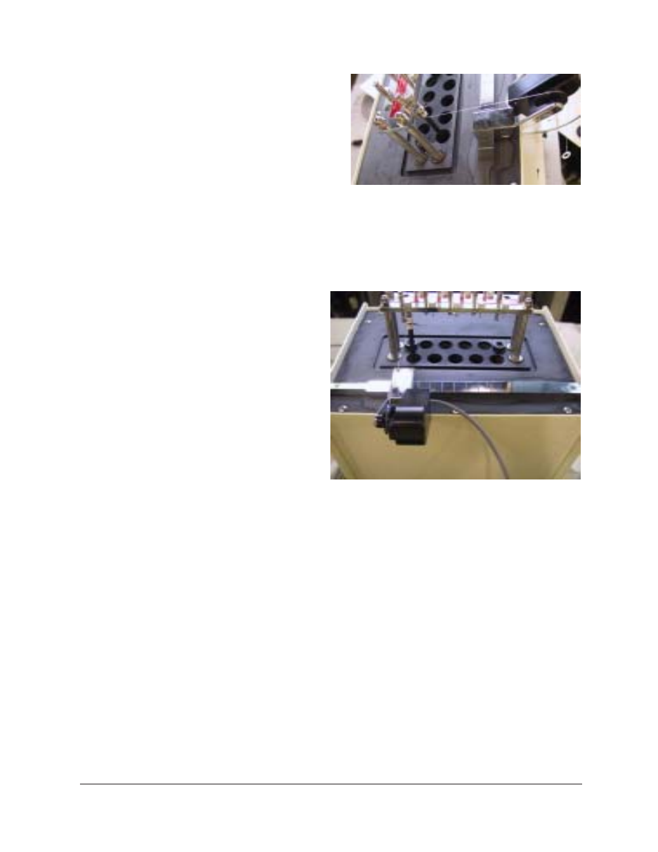
Pulley-wheel assembly
The pulley-wheel
assembly consists
of a V-channel
timing wheel with
a digital-optical
sensor permitting
precise measure-
ment of the wheel
rotation. The
pulley-wheel base
is designed to be
fitted to the
CMRV-4500 slide
track adjacent to
the viscometric
cells. The probe
cable is con-
nected to the jack on the front of the CMRV-4500 housing.
Winding thread
The thread used for CMRV-4500 testing is a single, nonelastic strand of
70 cm (28") winding thread of silk, cotton, or similar material (Coats
North America or comparable brand, 0.1 mm radius) with a loop on one
end. One end is wound around the CMRV-4500 rotor. The other end of
the thread is tied to a small rigid plastic ring from which the test weight
may be suspended.
Slide track
The pulley-wheel assembly is designed to interlock with the pulley-
wheel slide track and move laterally so it can be aligned with the scored
marks on the track opposite each of the nine rotor shafts.
String on rotor and pulley-wheel assembly
Slide track with pulley-wheel assembly