64
Appendix D: Cable Pinouts
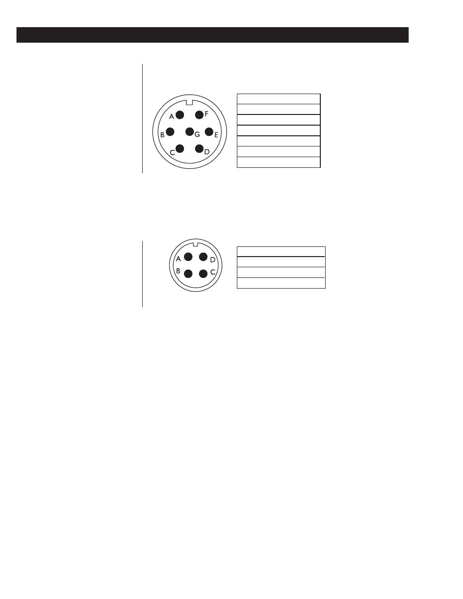
Below is an illustration of the loadcell interface cable and a table of pin assign-
ments.
A
- Signal
B
+ Excitation
C
+ Signal
D
- Excitation
E
- Sense
F
+ Sense
G
Ground
Loadcell Interface
Cable (7-pin connector)
A
Receive
B
Transmit
C
Clear to Send
D
Chassis Grnd
Four Pin Connector