And feedback voltage as needed. see, Direction, Feedback, & auto-mapping (proportional mep – KMC Controls MEP-7800 Series User Manual
Page 3
MEP-7200/7500/7800 Series
3
Installation Guide
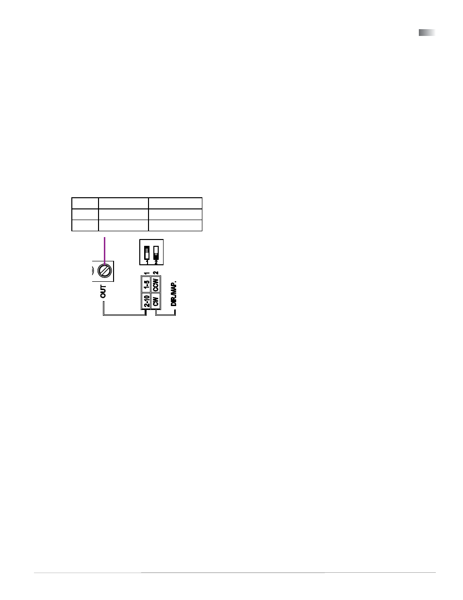
Illustration 6—Feedback Selector Detail MEP-7xx2
Direction, Feedback, & Auto-Mapping (Proportional MEP-7xx2 Models)
NOTE: The auto-mapping feature works best for
ranges that are more than about 45°.
To set the auto-mapping:
1. If desired, use the HMO-4536 adjustable end stop
kit to limit the stroke of the actuator.
2. With power applied to the actuator, flip selector
switch #2 (from its required CW or CCW
increasing voltage direction) to start the reset
mode. The actuator will first move to the CCW
limit. The complete reset process will take
approximately four minutes.
NOTE: On fail-safe models, wait for at least one
minute after power has been applied to
the actuator (allowing the capacitors to
fully charge) before initiating the automap
feature.
3. Return selector switch #2 to the required
increasing voltage direction before the reset
finishes. The reset process is complete after the
actuator has moved to the CW limit and has
begun to position normally.
4. Verify that the actuator travels completely across
the new range.
For example, after completing the auto-mapping
program, the new actuator stroke is 0–80°:
• Before Jan. 2014, a 5 VDC input signal (halfway
between 0–10 VDC) will drive the actuator to the
40° position (50% of its adjusted range) and the
feedback voltage will be 2.5 VDC if switch #1 is set
at the 0–5 VDC position or 5 VDC if switch #1 is
set at 0–10 VDC.
•
Starting in Jan. 2014, a 6 VDC input signal
(halfway between 2–10 VDC) will drive the
actuator to the 40° position (50% of its adjusted
range) and the feedback voltage will be 3 VDC if
switch #1 is set at the 1–5 VDC position or 6 VDC
if switch #1 is set at 2–10 VDC.
NOTE: The auto-mapping option is not available
with Master/Slave applications.
Proportional models offer selectable actuator rota-
tion direction and selectable proportional feedback
of 1–5 VDC or 2–10 VDC (in either direction).
To access the selector switches (see Illustration 6.),
loosen the screws on the conduit fitting and lift up to
remove the fitting. The selector switches are shipped
from the factory in the 1–5 VDC (#1) and CW move-
ment with increasing voltage (#2) positions.
*NOTE: Selector Switch #2 has two functions:
1. Switch #2 determines the direction to rotate
(CW or CCW) with increasing voltage and is
factory set in the CW position (down). To
change, remove power before flipping the
switch up to the CCW position. Removing
power prevents initiation of the auto-mapping
feature.
2. Switch #2 initiates the auto-mapping
feature. (See description below.) This feature
is initiated only by cycling the switch with
power applied to the unit. The auto-mapping
feature will NOT begin if the switch position
is changed with power removed or in the
event of a power failure.
MEP-7xx2 models also offer a actuator/signal range
reset program (auto-mapping) feature that reassigns
the full 2–10 VDC input signal scale over a reduced
stroke range for more precise control.
Switch (#1) Feedback
(#2)* Direction
Up
1–5 VDC
CCW
Down
2–10 VDC
CW
NOTE: Before Jan. 2014, MEP-7xx2 proportional
models had 0–10 VDC inputs and 0–5 or
0–10 VDC feedback. Starting in 2014, they
have 2–10 VDC inputs and 1–5 or 2–10
VDC feedback instead.
24 VAC/VDC
Power In
Feedback
Potentiometer
(MEP-7xx3 only)
24 VAC/VDC
Power In
24 VAC/VDC
Power In
2–10 VDC Control Signal
4–20 mA Control Signal
1–5 or 2–10 VDC Feedback Signal
Control Signal Common
(MEP-7x52 Only)
24 VAC/VDC
Power In
2
1
Switch/Contact
Jumper
Feedback
Potentiometer
(MEP-7xx3 only)
Feedback
Potentiometer
(MEP-7xx3 only)
CW
CCW
CW
CCW
1
2