Direction, feedback, and auto-mapping (mep-4xx2), Direction, feedback, and auto-mapping (mep – KMC Controls MEP-4800 Series User Manual
Page 3
MEP-4000/4800 Series
3
Installation Guide
Direction, Feedback, and Auto-Mapping (MEP-4xx2)
MEP-4xx2 models also offer a actuator/signal range
reset program (auto-mapping) feature that reassigns
the full 2–10 VDC input signal scale over a reduced
stroke range for more precise control.
NOTE: The auto-mapping feature works best for
ranges that are more than about 45°.
To set the auto-mapping:
1. If desired, use a 7/64-inch hex key wrench to
loosen and position the end-stop screw.
2. With power applied to the actuator, flip selector
switch #2 (from its required CW or CCW
increasing voltage direction) to start the reset
mode. The actuator will first move to the CCW
limit. The complete reset process will take
approximately four minutes.
3. Return selector switch #2 to the required
increasing voltage direction before the reset
finishes. The reset process is complete after the
actuator has moved to the CW limit and has
begun to position normally.
4. Verify that the actuator travels completely across
the new range.
For example, after completing the auto-mapping
program, the new actuator stroke is 0–80°:
• For current (starting Jan. 2014) MEP-40x2/48x2
actuators, a 6 VDC input signal (halfway between
2–10 VDC) will drive the actuator to the 40°
position (50% of its adjusted range) and the
feedback voltage will be 3 VDC if switch #1 is set
at the 1–5 VDC position or 6 VDC if switch #1 is
set at 2–10 VDC.
• For older
(before 2014) MEP-40x2/48x2 actuators,
a 5 VDC input signal (halfway between 0–10
VDC) will drive the actuator to the 40° position
(50% of its adjusted range) and the feedback
voltage will be 2.5 VDC if switch #1 is set at the
0–5 VDC position or 5 VDC if switch #1 is set at
0–10 VDC.
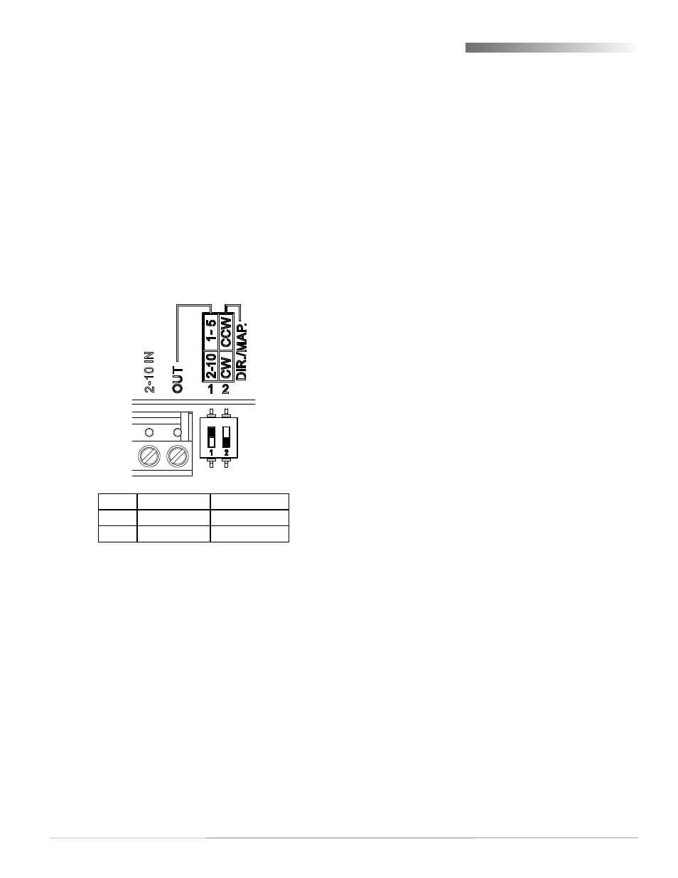
MEP-4xx2 proportional models offer selectable
actuator direction and selectable proportional feed-
back of 1–5 VDC or 2–10 VDC (in either direction).
To access the selector switches, loosen the screw on
the tethered cover and remove the cover. The selec-
tor switches are shipped from the factory in the 1–5
VDC (#1) and CW movement with increasing voltage
(#2) positions (see Illustration 6).
Illustration 6—Feedback/Direction/Mapping Selectors
*NOTE: Selector Switch #2 has two functions:
1. Switch #2 determines the direction to rotate
(CW or CCW) with increasing voltage and is
factory set in the CW position (down). To
change, remove power before flipping the
switch up to the CCW position. Removing
power prevents initiation of the auto-mapping
feature.
2. Switch #2 initiates the auto-mapping
feature. (See description below.) This feature
is initiated only by cycling the switch with
power applied to the unit. The auto-mapping
feature will NOT begin if the switch position is
changed with power removed or in the event
of a power failure.
Switch (#1) Feedback
(#2)* Direction
Up
1–5 VDC
CCW
Down
2–10 VDC
CW
NOTE: Before Jan. 2014, MEP-40x2/48x2 models
had 0–10 VDC inputs and 0–5 or 0–10
VDC feedback instead. When replacing an
older 0–10 VDC actuator with a 2–10 VDC
actuator, make note of the differences.
NOTE: For more information (including
adjustments, accessories, troubleshooting,
torque selection, and links to sample
applications), see the
on the