KMC Controls MEP-4800 Series User Manual
Installation guide, Direct-coupled controlset, Actuators (40/80 in-lb.)
MEP-4000/4800 Series
1
Installation Guide
Installation Guide
Direct-Coupled ControlSet
®
Actuators (40/80 in-lb.)
MEP-4000/4800 Series
Direction, Feedback, and Auto-Mapping (MEP-4xx2)
Maintenance 4
More Information 4
Mounting
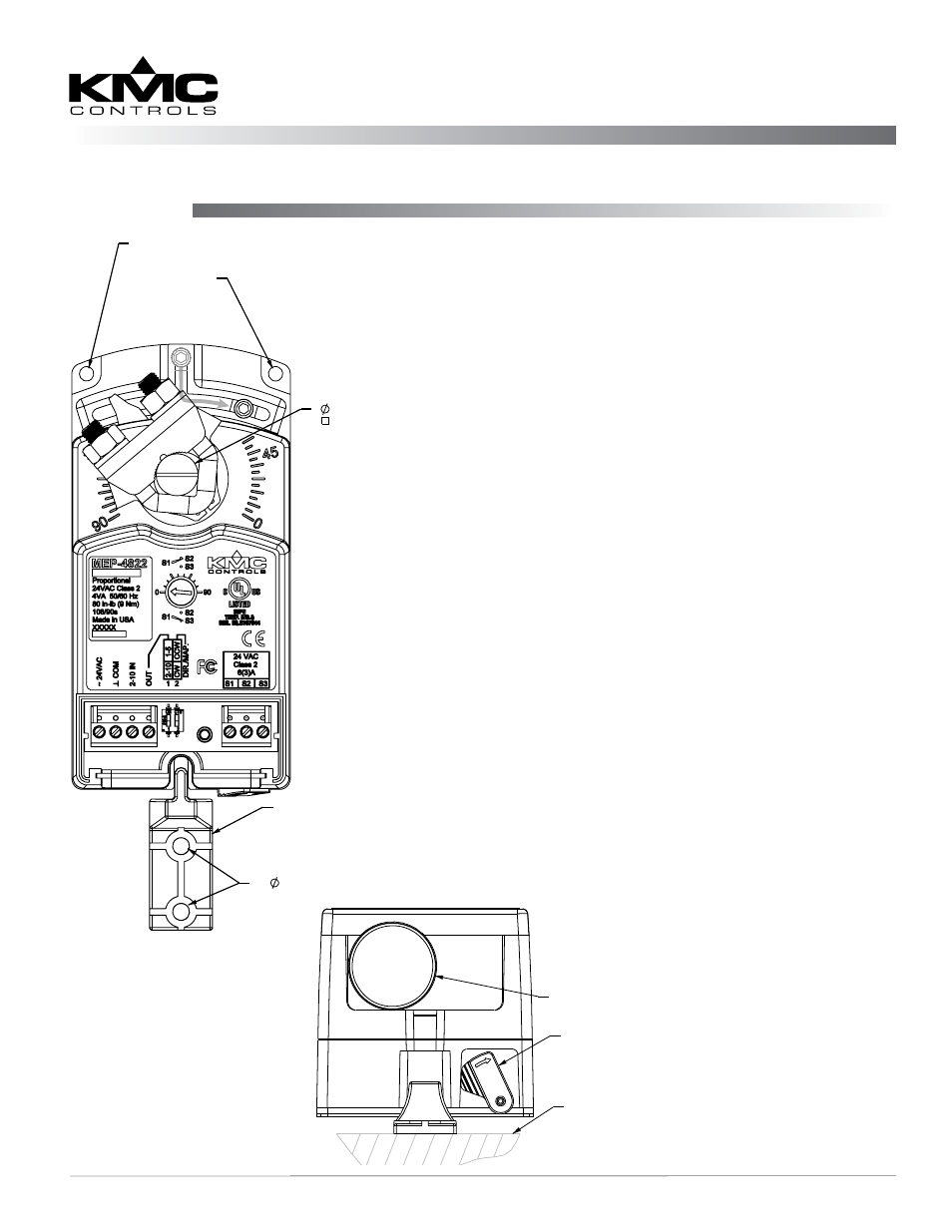
Illustration 1—Overview
(Direct-Coupled Mounting)
1. Ensure the damper can move freely through its
entire range of motion, and fix any binding before
installing the actuator. Turn the damper blade to
its fully closed position.
2. Press (to the right) and hold the gear
disengagement lever (see Illustration 1), rotate the
actuator to the fully closed position, and release
the lever.
NOTE: Depending on the damper-seal design,
backing the actuator off its stop
approximately 5° may provide tight
damper shut-off.
3. Align the actuator and slide it onto the shaft.
4. Leaving a gap between the actuator and
mounting surface to prevent any binding, finger-
tighten the nuts on the V-bolt.
5. Insert the non-rotation bracket (HMO-4002
supplied or HMO-4001 “T” bracket available
separately) into the slot at the base of the actuator.
(See Illustration 1).
6. Secure the non-rotation bracket with two (2) #8 or
#10 self-tapping screws.
7. Evenly tighten the V-bolt nuts 30–35 in-lb. on
MEP-4000s or 60–70 in-lb. on MEP-4800s.
8. If desired, use a 7/64-inch hex key wrench to
loosen and position the end-stop screw.
NOTE: The two holes at the top of the actuator
are NOT for use in direct-coupled
applications. They are for remote
mounting, such as with the optional HLO-
4001 Crank Arm Kit (
ADJUSTABLE
END STOP
THESE HOLES ARE FOR USE IN
REMOTE MOUNTING SITUATIONS—
DO NOT USE IN DIRECT COUPLED
APPLICATIONS
0.200 (5mm)
NON-ROTATION BRACKET
(HMO-4002)
1/4" to 5/8" (6 to 16mm)
1/4" to 7/16" (6 to 11mm)
(2)
GEAR
DISENGAGEMENT
LEVER
MOUNTING
SURFACE
REMOVEABLE CONDUIT FITTING
WITH 1/2" NPS THREADED HOLE