Fail-safe direction, Auxiliary switch (mep-4x7x), Auxil – KMC Controls MEP-4900 User Manual
Page 3
MEP-4200/4500/4900 Series
3
Installation Guide
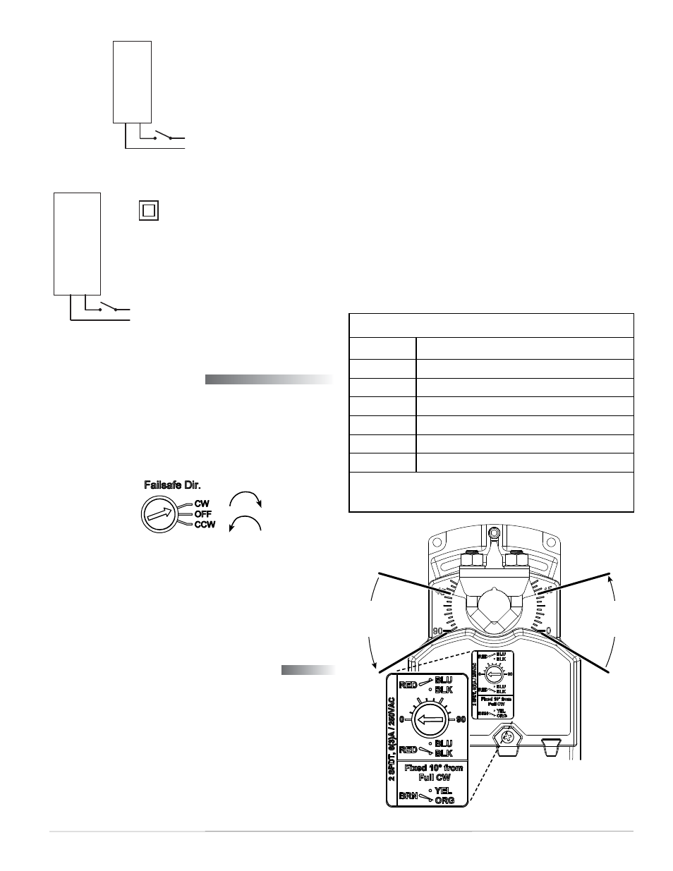
Illustration 7—MEP-4xx4 Two-Position (2-Wire) 24 VAC/VDC
Illustration 8—MEP-4xx5 Two-Position (2-Wire) 100–240 VAC
Illustration 10—Actuator Rotation and (MEP-497x) Aux. Switch
Auxiliary Switch (MEP-4x7x)
In MEP-4x7x models, the adjustable auxiliary SPDT
switch can be set to trip anywhere between 0° (full
CW rotation position) and 90° (full CCW). To adjust
the auxiliary switch position:
1. While pressing the gear disengagement lever (see
Illustration 1), rotate the actuator to the point
where the auxiliary switch should trip.
2. Using a small, flat-bade screwdriver, adjust the
rotary dial to “0” (see Illustration 10). As the
Auxiliary Switch Cable*
Wire Color
Function
Red
Adjustable Aux. Switch, Common
Blue
Adjustable Aux. Switch (see Illustration 10)
Black
Adjustable Aux. Switch (see Illustration 10)
Brown**
Fixed Aux. Switch, Common
Orange**
Fixed Aux. Switch, Closed 0–10°
Yellow**
Fixed Aux. Switch, Closed 11–90°
*Left-hand cable, looking from the top (see Illustration 2).
**Fixed auxiliary switches (with brown, yellow, orange wires) are
only available in MEP-497x models.
Illustration 9—Fail-Safe Direction Switch Dial
Fail-Safe Direction
All models offer selectable fail-safe direction. Pro-
portional and tri-state models also offer the option
to turn the fail-safe off (see Illustration 9). Using a
small, flat-bade screwdriver, adjust the switch dial to
the desired clockwise or counterclockwise direction.
NOTE: After initial connection or reconnection to
power on MEP-4xx2 proportional models,
proper fail-safe operation might be delayed
up to 30 seconds (until the capacitors are
fully charged).
Line/Hot
Neutral
(L1) Neutral (Blac
k)
(L2) Line (Red)
100–240 VAC Power
NOTE: Double Insulated. Meets UL
requirements without the need
of an electrical ground connection.
–
Power Supply
24 VAC/VDC
T COM (Blac
k)
~24
V (Red)
~/+
Rotation
Indication
(0–45°)
Auxiliary
Switch
Setting
Dial
Actuator Shown
At 45° Rotation
Rotation
Indication
(45–90°)
actuator rotates, the switch dial arrow will point
to the current switch position (Red connected to
Blue vs. Red connected to Black). For example,
if the switch is set to trip (dial at “0”) when the
actuator rotation position is at 45°, then Red is
connected to Black from 0° to 45°, and Red is
connected to Blue from 45° to 90°.
NOTE: On MEP-497x models, a second switch is
fixed at 10° from full CW direction (Brown
is connected to Orange in the 0–10° range,
and Brown is connected to Yellow 11–90°).
3. Wire the desired auxiliary device(s) to the cable.
NOTE: For more detailed information, see the
on the KMC
web site.
NOTE: The SPDT switch is rated for 6 A with resis-
tive load or 3 A with motor load @ 250 VAC.