Wiring, Wiring 2, Caution attention – KMC Controls MEP-4900 User Manual
Page 2
MEP-4200/4500/4900 Series
2
Installation Guide
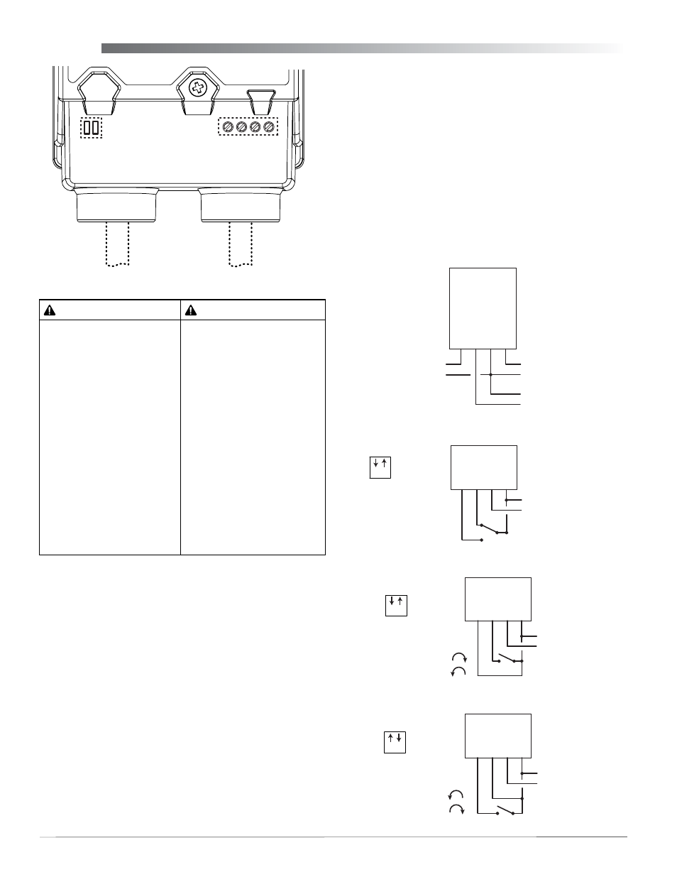
Wiring
Depending on the model, signal/power wiring might
be to terminals under the conduit fitting or to color-
coded wires in the attached cable. See Illustration 2.
Consult the model label and the appropriate wiring
shown in Illustrations 3 through 8.
For auxiliary switch wiring and setting, see
iary Switch (MEP-4x7x) on page 3
For models withOUT the attached signal/power
cable:
1. Loosen the screw on the
conduit fitting and lift up
to remove the fitting.
2. Using a utility knife or drill, cut the red plug
to accept wiring or replace the plug with an
application-specific fitting.
NOTE: The red plug (or similar fitting) protects
internal components from debris, helping
to ensure long actuator life.
Power/Signal
Terminal Block
Selector
Switches
Power/Signal
Cable
Aux. Switch
Cable
(Under Conduit Fitting)
Illustration 2—Cables and Terminal Block Options
Illustration 3—MEP-4xx2 Proportional Control
–
–
–
~/+
+
Control Signal
2–10 VDC
Power Supply
24 VAC/VDC
OUT (Green)
2–10 IN (White)
T
COM (Blac
k)
~24
V (Red)
+
Feedback Output
1–5 or 2–10 VDC
Illustration 4—MEP-4x51 Tri-State Floating Point Control
–
Power Supply
24 VAC/VDC
CW
CCW
T COM
~24 V
~/+
–
Switch
Position
1 2
Illustration 6—MEP-4x51 2-Position Control (4-Wire), CW Leg
–
Power Supply
24 VAC/VDC
Contact Position:
Closed = CW Rotation
CW
CCW
T COM
~24 V
~/+
Open = CCW Rotation
Switch Position
1 2
Illustration 5—MEP-4x51 2-Position Control (4-Wire), CCW Leg
–
Power Supply
24 VAC/VDC
Contact Position:
Closed = CCW Rotation
CW
CCW
T COM
~24 V
~/+
Open = CW Rotation
Switch Position
1 2
3. Thread wires through the plugged opening and
connect to the terminal block according to the
relevant model and application.
4. For MEP-4xx2 models, adjust the feedback
voltage, direction, and automapping as needed.
Direction, Feedback, and Auto-Mapping
models, adjust the selector switch as shown in
Illustrations 2 and 4–6.
5. Reinstall the conduit fitting and tighten the screw.
NOTE: After initial power-up, proportional models
have a 30-second delay of motor operation.
CAUTION
ATTENTION
Risk of electrical shock.
Disconnect ALL power
before servicing. More than
one disconnect provided
on models with auxiliary
switches. Failure to follow
electrical safety precautions
with live electrical
components could result in
injury or death.
If both conduit connections
are used, they MUST be
externally connected during
installation. The nonmetallic
enclosure does not provide
grounding connection
between the two conduit
connections.
Risque de choc électrique.
Débranchez l’alimentation
avant l’entretien. Plus d’un
sectionneur fourni sur les
modèles avec contacts
auxiliaires. L’inobservation
des consignes de sécurité
électrique avec des
composants électriques sous
tension peut entraîner des
blessures ou la mort.
Si les deux entrées de câble
sont utilisés, ils doivent être
connectés en externe lors de
l’installation. Le boîtier non-
métallique n’assure pas la
connexion à la terre entre les
deux connexions.