24 vac/dc – KMC Controls MEP-425 Series User Manual
Page 5
Document No. 129-360
Installation Instructions
Rev. 1, December, 2001
Page 5 of 7
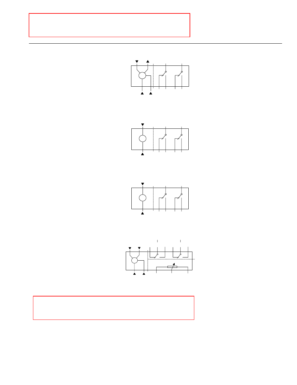
MEP-4256xx
SWITCH
A
SWITCH
B
DUAL AUXILIARY
SWITCHES
S1
S4
S2
S3
S5
S6
EA0867R1
N.C. N.O.
N.C. N.O.
COMMON COMMON
M
NEUTRAL
SUPPLY
OUTPUT
INPUT
1
8
9
2
24 Vac/dc
Continuous control DC
0...10V
Commande progressif DC
0...10V
Control continuo 0...10V
CC
MEP-425100
M
SWITCH
A
SWITCH
B
DUAL AUXILIARY
SWITCHES
S1
S4
S2
S3
S5
S6
2
1
EA0864R1
NEUTRAL
N.C. N.O.
N.C. N.O.
COMMON
SUPPLY
COMMON
24 Vac/dc
2-position control
Commande tout ou rien
Control a 2 puntos
MEP-425300
M
SWITCH
A
SWITCH
B
DUAL AUXILIARY
SWITCHES
S1
S4
S2
S3
S5
S6
4
3
EA0955R1
NEUTRAL
N.C. N.O.
N.C. N.O.
COMMON
LINE
COMMON
120 Vac
2-position control
Commande tout ou rien
Control a 2 puntos
MEP-4255xx
M
1000 OHMS
0%
100%
P1
0 TO 100%
P1 TO P2
P3
100 TO 0%
P2 TO P3
P2
COMMON
FEEDBACK POTENTIOMETER
DUAL AUXILIARY SWITCHES
NEUTRAL
SUPPLY
S2
S1
S3
N.C.
CCW
CW
N.O.
SWITCH A
COMMON
S5
S4
S6
N.C.
N.O.
SWITCH B
COMMON
1
6
7
2
EA0873R1
24 Vac/dc
3-position control
Commande 3 points
Control a 3 puntos
NOTE: These wiring diagrams show options that are no
longer available for certain models. To order models with the
appropriate options, see the MEP-425 series data sheet!
NOTE: Do not order actuator models based on these
diagrams! To order models with the appropriate options, see
the MEP-425 series data sheet.