Connections and wiring, All models, Tsp-5002/5022 proportional models – KMC Controls TSP-5000 Series User Manual
Page 2: Tsp-5003/5023 tri-state models, Connections and wiring 2
TSP-5000 Series
2
Installation Guide
Connections and Wiring
All Models
1. Remove the TSP-50xx’s wiring access door by
pulling back on the door’s tab and lifting upward.
2. Access for wire or cable is via two 5/8" (16 mm)
diameter snap-in shutter bushings located on the
bottom of the cover.
3. Remove the snap-in shutter bushing and replace
with one the following connectors as needed.
(Connectors not supplied, order separately):
a. HMO-4518 for 1/2" flexible conduit.
b. HMO-4520 compression connector for plenum
rated cable.
c. HMO-4526 for rigid 1/2" conduit.
NOTE: Continue to the appropriate 2–10 VDC
proportional or tri-state model section.
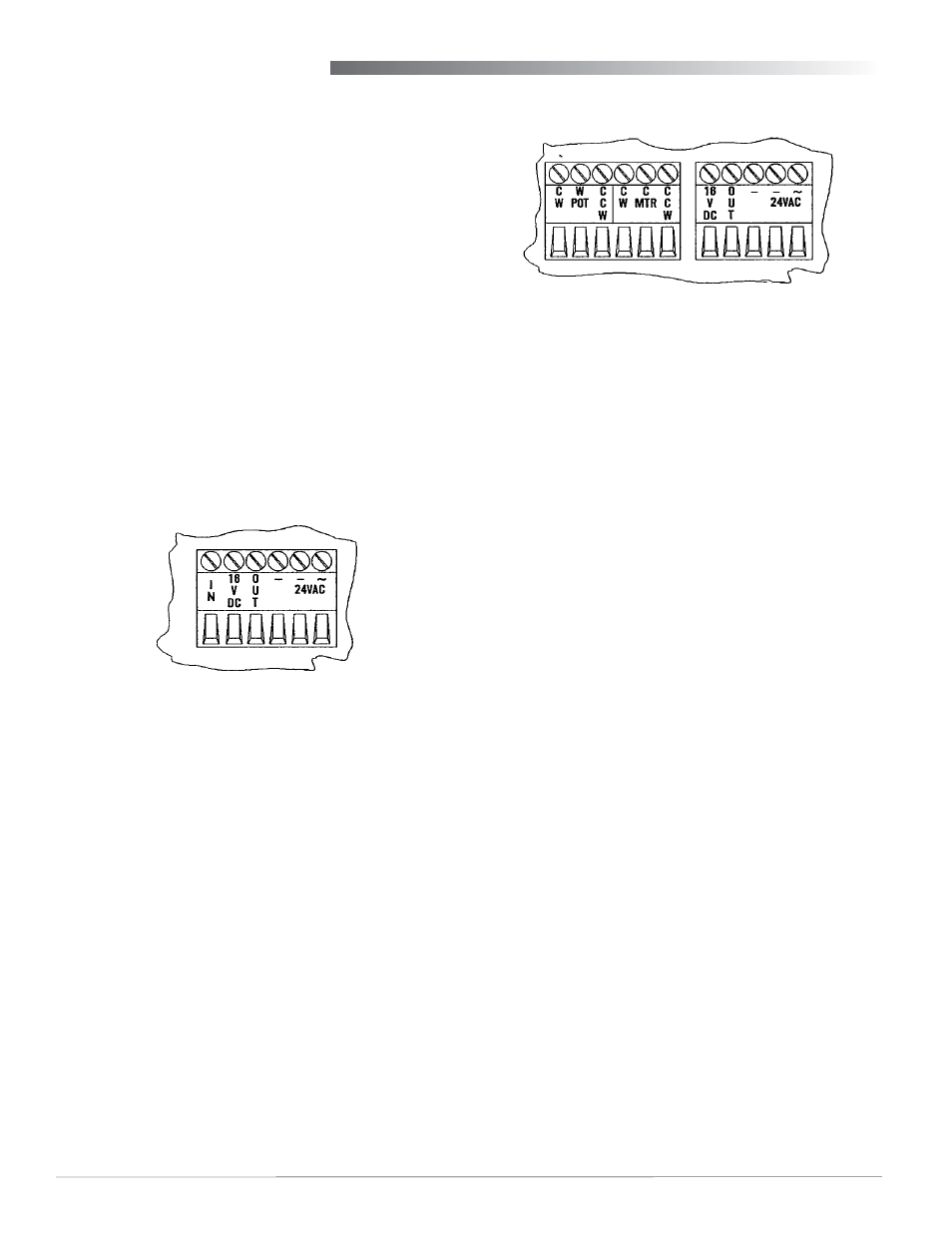
TSP-5002/5022 Proportional Models
4. Wire the tri-state TSP-50x3 as follows:
a. Terminal “CW” (just left of “W POT”) for one side
of the 10K potentiometer (1/3 watt) for optional
position feedback to a controller input.
b. Terminal “W POT” (Wiper Potentiometer) for the
wiper of the 10K pot.
c. Terminal “CCW” (just right of “W POT”) for the
other side of 10K pot.
d. Terminal “CW” (just left of “C MTR”) to 24
VAC clockwise motor drive.
e. Terminal “C MTR” (Common Motor) to
common for CW or CCW motor drive.
f. Terminal “CCW” (right of “C MTR”) to 24
VAC CCW motor drive.
g. Terminal “OUT” (+ output) optional air velocity
readout signal.
h. Terminal “16 VDC” (optional 22 mA power
supply).
i. Terminal “–” optional air velocity readout
reference (and 16 VDC reference if required).*
j. Terminal “–” to the neutral or ground side of
the transformer.*
k. Terminal “~” to the phase side of a 24 VAC
–15/+20%, 50/60 Hz, Class 2 only transformer.
*NOTE: Both “–” terminals are internally connected.
5. Reinstall the wiring access door.
TSP-5003/5023 Tri-State Models
4. Wire the proportional TSP -50x2 as follows:
a. Terminal “IN” to 2–10 VDC proportional
signal from thermostat/controller.
b. Terminal “16 VDC” (optional 22 mA power
supply).
c. Terminal “OUT” (+ output) optional air velocity
readout signal.
d. Terminal “–” thermostat/controller signal and
air velocity readout reference (and 16 VDC
reference if required).*
e. Terminal “–” to the neutral or ground side of
the transformer.*
f. Terminal “~” to the phase side of a 24 VAC
–15/+20%, 50/60 Hz, Class 2 only transformer.
*NOTE: Both “–” terminals are internally connected.
5. Reinstall the wiring access door.